Mounting and connecting the device
3.4 Connecting the device
Unified Comfort Panels
44 Operating Instructions, 03/2020, A5E46641217-AA
3.4.3 Connecting the power supply
Safe electrical isolation
For the 24 V DC supply, only use power supply units with safe electrical isolation according
to IEC 61010-2-201, e.g. according to the SELV/PELV standard.
The supply voltage must be within the specified voltage range. Otherwise, malfunctions at
the HMI device cannot be ruled out.
The following applies for a non-isolated system design: Connect the GND 24 V connection
from the 24 V power supply output to equipotential bonding for uniform reference potential.
You should always select a central point of termination.
External protective circuit
An external protective circuit is required for operation with 24 V DC, see section 7
"Lightning protection and overvoltage protection" in function manual "Designing
interference-free controllers
(https://support.industry.siemens.com/cs/ww/en/view/59193566)".
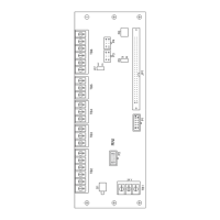
Wiring diagram
The following figure shows the connection between the power supply and the HMI device
with the Unified Comfort Panel with display diagonal ≥15" as an example.
 Loading...