Analog Modules
4-173
Programmable Logic Controllers S7-300 Module Data
A5E00105505-03
Module filtering mode: Synchronicity
In synchronous operation the following conditions apply:
Processing and activation time T
WA
between reading the output
value into the output buffer and loading it into the D/A converter for
the output
1.6 ms
T
DPmin
2.4 ms
Diagnostic interrupt max. 4 x T
DP
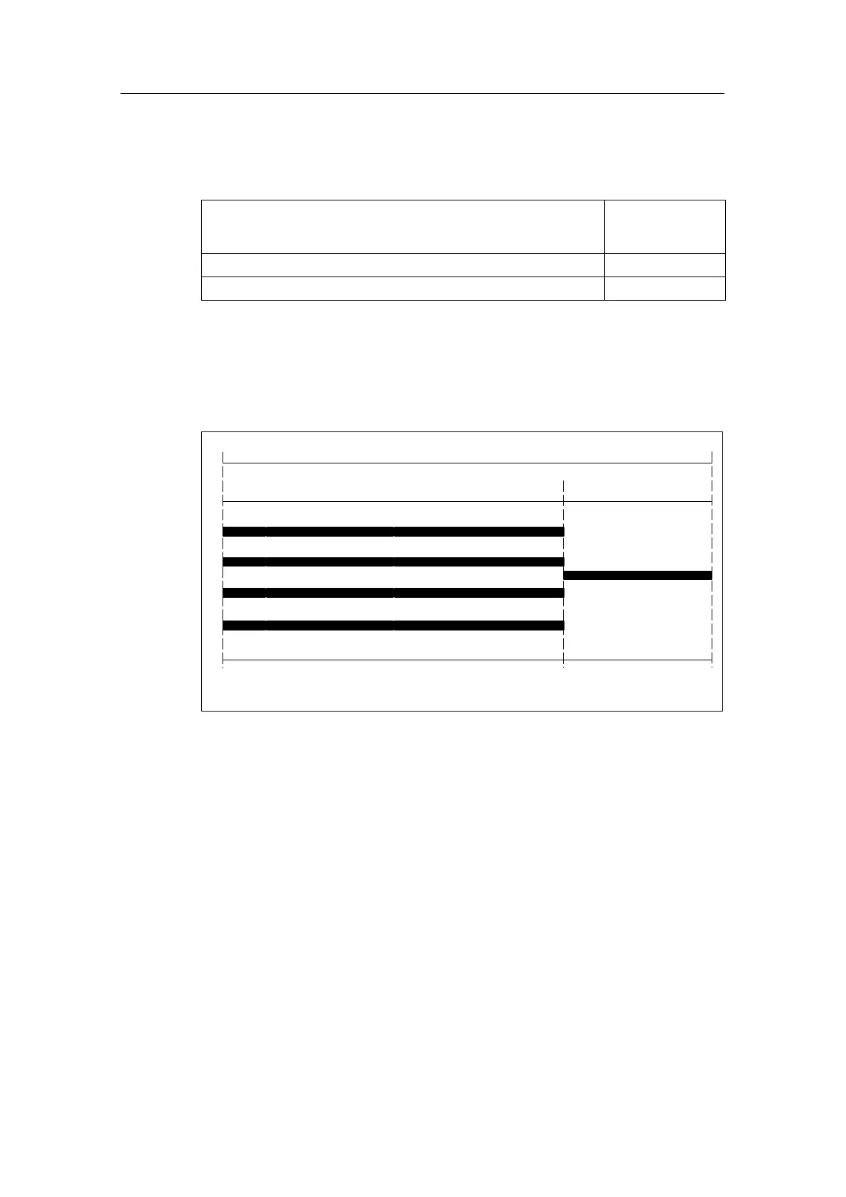
Calculation of the filter and processing time
Independent of the number parameterized channels the same time conditions are
always valid.
CH3
CH2
CH1
CH0
200s
D/A conversion and internal processing
Updating of the
output
T
WA
T
O
1400s
Figure 4-52 Calculation of the processing time and the time for updating the output
Explanation of the mode of operation in synchronous operation
During the time T
O
- T
WA
, the module reads the output data and saves the data
internally. After the internal processing time of each channel the results are written
in the individual D/A converters.
Further information
Further information on clock synchronicity can be found in the Online help of
STEP 7, in the manualLocal Peripheral System ET 200M and in the manual
Clock Synchronicity.
 Loading...


