Interrupts, diagnostics, error, and system messages
5.1 Status and error displays
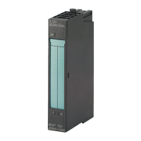
IM 155-6 PN ST interface module (6ES7155-6AU01-0BN0)
28 Equipment Manual, 10/2020, A5E03576904-AE
PWR LED on the interface module
Table 5- 2 PWR status display on the interface module
Supply voltage not present or too small
Check the supply voltage.
LK1/LK2 LED on the BusAdapter
Table 5- 3 LK1/LK2status display on the BusAdapter
Off
There is no Ethernet connection between the
PROFINET IO interface of your PROFINET device and
a communication partner (e.g. IO controller).
Check whether the bus cable to the switch/IO con-
troller is interrupted.
On
There is an Ethernet connection between the
PROFINET IO interface of your PROFINET device and
a communication partner (e.g. IO controller).
The "Node flash test" is run (the RN/ER/MT LEDs also
flash).
LED display of configuration errors
Configuration errors of the ET 200SP distributed I/O system are output on the
interfacemodule by the ERROR (red) and MAINT (yellow) LEDs.
The following configuration errors are indicated by the LEDs:
• More than one I/O module pulled
• Missing server module
• Interruptions or short circuit on the backplane bus
Principle of operation
You determine the information for cause of the error with the LED error display. After
notification by the flash signal, the error type is displayed followed by the error location/error
code.
The LED error display
• is active during POWER ON as well as during operation.
• has priority before all other states displayed by the ERROR and MAINT LED.
• remains turned on until the cause of the error has been corrected.
 Loading...