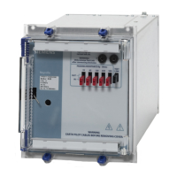
7PG21 Solkor Rf Description of Operation
Contents
1 General .............................................................................................................................................................. 3
2 Description ......................................................................................................................................................... 4
3 Operation ........................................................................................................................................................... 6
4 Theory of Summation Transformer................................................................................................................... 13
List of Tables
Figure 1 Solkor Rf schematic...............................................................................................................................4
Figure 2 Solkor R schematic................................................................................................................................4
Figure 3 Solkor Rf 15kV schematic .....................................................................................................................5
Figure 4 Through Fault, zero ohm pilots, Positive half cycle. ..............................................................................7
Figure 5 Through Fault, zero ohm pilots, Negative half cycle..............................................................................7
Figure 6 Through Fault, 1000 ohm pilots, Positive half cycle. .............................................................................8
Figure 7 Through Fault, 1000 ohm pilots, Positive half cycle. .............................................................................8
Figure 8 Through fault Rf mode, positive half cycle.............................................................................................9
Figure 9 Through fault Rf mode, negattive half cycle ..........................................................................................9
Figure 10 Through fault Rf mode, positive half cycle.........................................................................................10
Figure 11 Through fault Rf mode, positive half cycle.........................................................................................10
Figure 12 Internal fault Rf mode, positive half cycle ..........................................................................................11
Figure 13 Internal fault Rf mode, positive half cycle ..........................................................................................11
Figure 14 Single End Fed fault Rf mode, positive half cycle..............................................................................12
Figure 15 Single End Fed fault Rf mode, negative half cycle ............................................................................12
©2011 Siemens Protection Devices Limited Chapter 1 Page 2 of 13

 Loading...


