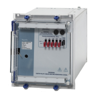
7PG21 Solkor Rf Installation
Contents
1 Unpacking, storage and handling....................................................................................................................... 3
2 Recommended Mounting Position...................................................................................................................... 3
3 Relay Dimensions .............................................................................................................................................. 3
4 Fixings................................................................................................................................................................ 3
4.1 Epsilon Cases............................................................................................................................................ 3
4.1.1 Crimps............................................................................................................................................ 3
4.1.2 Panel Fixing Screws ....................................................................................................................... 4
4.2 Vedette Cases ........................................................................................................................................... 4
4.2.1 Crimps............................................................................................................................................ 4
4.2.2 Panel Fixing.................................................................................................................................... 4
4.3 Back of Panel cases .................................................................................................................................. 4
4.3.1 Crimps............................................................................................................................................ 4
4.3.2 Mounting arrangement.................................................................................................................... 4
Table of Figures
Figure 1. E2 Case................................................................................................................................................5
Figure 2. E4 Case................................................................................................................................................5
Figure 3. E6 Case................................................................................................................................................5
Figure 4. Vedette C1½ Case ...............................................................................................................................6
Figure 5. 15kV Transformer Outline & Mounting Arrangement............................................................................7
Figure 6. Intertripping Inverter Outline and Mounting Arrangement.....................................................................7
©2010 Siemens Protection Devices Limited Chapter 5 Page 2 of 7

 Loading...


