9200 Features Guide
12
Configuration Mode
You must set the PTS (PT Scaling) register to “x1000” for the correct
operation of a meter with the Megawatt option. Refer to the section
“Before You Use the Megawatt Option” on page 6. To learn about
Configuration mode, refer to the 9200 Installation and Basic Setup
Instructions.
Configurable Meter Settings
Configurable meter settings are listed in “Meter Settings” on page 21.
V
A
R
AVG
V
VA
PF
x 1000
AVG
I
FREQ
W
4
I
x 1000
x 1000
k
M
M
M
MAX
DMD
MIN
kWh kVAh kVARh
A
C
5.
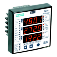
Peak Demand Measurements
Peak (Max) Demand measurements include Total Power Peak
Demand, and Total Current Peak Demand. The example above
shows VA), Reactive
Power (MVAR), and Real Power (MW).
Total Power Peak Demand for: Apparent Power (M
The values are: 251.9 MVA;
96.0 MVAR; and 232.9 MW.
Press the Enter button to return to measurements.System
Press the Up/Down
buttons to toggle be-
tween Total Power/Total
Current Peak Demand
OR
MAX
DMD
MIN
THD
I
LN
V
LL
V
I
k
k
Demand/Max
measurements
VAR
AVG
V
VA
PF
x 1000
AVG
I
FREQ
W
4
I
x 1000
x 1000
k
M
M
M
 Loading...