81 / 92
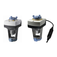
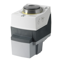
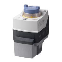
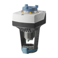
Siemens Actuators SAX.., SAY.., SAV.., SAL.. for valves CE1P4040en
Building Technologies Connection diagrams and dimensions 2018-12-05
6.2 Connection terminals
6.2.1 Actuators
AC 230 V, 3-position
System neutral (SN)
Positioning signal (actuator’s stem extends / actuator’s spindle turns clockwise)
Positioning signal (actuator’s stem retracts / actuator’s spindle turns counter-clockwise)
AC/DC 24 V, DC 0…10 V / 4…20 mA / 0…1000 Ω
Sytem neutral (SN)
System potential (SP)
Positioning signal for DC 0…10 V / 4…20 mA
Measuring neutral
Position feedback DC 0...10 V - (reference potential is M measuring neutral)
Positioning signal forced control AC/DC ≤ 24 V, 0...1000 Ω
AC/DC 24 V, Modbus RTU connection cable
System neutral (SN)
System potential (SP) AC 24 V ~ / DC 24 V ⎓
Reference (Modbus RTU)
Bus + (Modbus RTU)
Bus - (Modbus RTU)
black
red
violet
grey
pink
AC/DC 24 V, 3-position
System potential (SP)
Positioning signal (actuator’s stem extends / actuator’s spindle turns clockwise)
Positioning signal (actuator’s stem retracts / actuator’s spindle turns counter-clockwise)
6.2.2 Electrical accessories
Adjustable switching points, AC 24…230 V
System potential (SP)
Closing Contact
Opening Contact
Switching state allway’s related to extending actuator stem or
clockwise turning actuator’s spindle turns
Adjustment of zero point, DC 10 V
Measuring neutral
0…x Ω
x…0 Ω
x = 135 Ω, 200 Ω;1000 Ω
AC/DC 24 V / 30 W / 50 VA / inrush current max. 8.5 A
System neutral (SN) (red)
System potential (SP) (black)
AC 24 V...230 V / 6 (2) A
S1
SA..31..
SA..61..
SAX61../MO
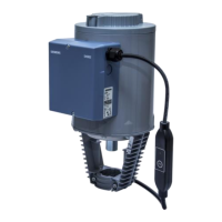
Fixed connecting cable
5 x 0.75 mm
2
SA..81..
Auxiliary switch
ASC10.51
Potentiometer
ASZ7.5
Stem heating element
ASZ6.6

 Loading...

