Siemens Building Technologies CM2N3204E / 1.1999
Landis & Staefa Division 3/20
• Room-supply air temperature or extract air-supply air temperature cascade control.
The connection of room or extract air temperature detectors (terminal B1) and supply
air temperature detectors (terminal B2) automatically activates cascade control.
With cascade control, the room or extract air temperature is maintained at a constant
level. The room or extract air temperature is the controlled variable whose setpoint
can be read off and adjusted on the controller’s second operating level.
The supply air temperature is shifted in function of the deviation of the room / extract
air temperature from the setpoint of room / extract air temperature. The extent of set-
point shift is calculated via the cascade authority (adjustable from 0 to 20).
- Room-supply air temperature or extract air-supply air temperature cascade control
with fixed supply air limitations (mode of control 1).
If the supply air temperature falls below the limit set on the controller, the inbuilt
minimum limitation will take command of control to prevent the supply air tempera-
ture from falling further.
The set limit is maintained at a constant level. The same considerations apply to
maximum limitation.
- Room-supply air temperature or extract air-supply air temperature cascade control
with shifting supply air limitations (displacement ventilation) (mode of control 2).
The shifting limits of the supply air temperature are calculated in function of the ac-
tual room or extract air temperature, whereby the supply air temperature must re-
main within the boundaries dictated by the selected values of minimum and maxi-
mum limitation.
• Supply air temperature control (mode of control 3).
If a supply air temperature detector (terminal B2) is connected, supply air temperature
control is automatically activated. With this mode of control, the supply air temperature
is maintained at a constant level.
The required mode of control can be selected.
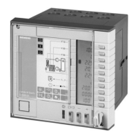
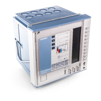
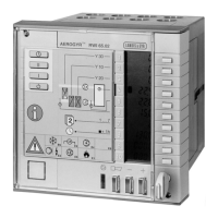
The RWI65.02 is a sequence controller with three modulating outputs (Y10 = heating,
Y20 = cooling, Y30 = HR) and one switching output (Q13/Q24 = cooling).
It allows control sequences using both operating actions, for dampers and HR equip-
ment. Both operating action and control sequences are adjustable (DIL switches no. 4
to 7).
100
Y30
min
Y10/Y30 Y30/Y10
Y20
SA
SD
T
w
h
w
c
X
P1
T
n1
X
P3
T
n3
X
P2
T
n2
Y [ % ]
3204D03E
(DtPnt 33)
(DtPnt 32)
(DtPnt 6)
The basis used for compensation are the setpoints selected on the controller. These
basic setpoints can be shifted as follows:
• compensation of controller setpoint in function of the outside temperature (terminal
B4); with this function, summer/winter compensation is integrated in the controller; the
compensation characteristic is adjustable
• compensation by means of an active or passive setting unit, either as an absolute
setpoint or in the form of setpoint shifting via signal input «Z»
• compensation across the entire setpoint range by a Landis & Staefa building auto-
mation system via the FLN bus and FLN communication insert AZI65.1
Temperature control
Control sequences
and operating action
Function diagram
Setpoint compensation
 Loading...
