CM2N3204E / 1.1999 Siemens Building Technologies
6/20 Landis & Staefa Division
T Temperature in the hot water heating coil’s circuit, or air temperature just after the heating coil
Q Load
Y Manipulated variable
Y10 Control command «Heating valve»
Q13/Q14 Relay output «Hot water circulator or electric air heater battery»
Q33/Q34 Relay output «Fan speed I»
Q33/Q44 Relay output «Fan speed II»
X
pd
P-band «Frost protection controller» (data point 18)
X
pn
P-band «Standby controller» (data point 19)
w
w
Frost alarm value (data point 16)
w
wn
Setpoint «Standby controller» (data point 17)
t
Pmin
Min. running time of hot water circulator (data point 48)
The startup mode is only used with the heating sequence Y30 with operating action «/»
(plants using recirculated air dampers). On plant startup, supply air temperature control
or one of the two cascade control modes is activated.
The period of time for startup mode can be set from 0 s to 60 min. During this time, the
cooling sequence (Y20) is disabled and the hot water circulator (Y10) is activated. The
plant operates with 100 % recirculated air (prepurging).
In the case of plants that use outside detectors, this function becomes active only at
outside temperatures below 15 °C.
In the case of plant startups initiated by «Unoccupied heating mode», «Unoccupied
cooling mode» or «Night purging», this function remains inactive.
Plant operation can be controlled from the following locations:
manual switch (operating level 1: buttons 1 to 4), communication (FLN bus), «External
switch» (E7, E8), «Extended operation» (E7, E8), time switch program, «Demand con-
trolled ventilation», «Unoccupied heating mode», «Unoccupied cooling mode», night
purging, fault, commissioning.
• From an external switch:
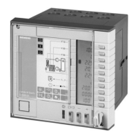
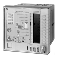
the functions of the manual switch on the RWI65.02 (operating level 1, buttons 1 to 4)
can be provided by a 4-step rotary switch with two levels.
• By the function «Extended operation»:
when a pulse (of at least 3 s) is fed to E7, the plant will be operated at fan speed I;
when a pulse (of at least 3 s) is fed to E8, the plant will be operated at fan speed II.
• Time switch program:
the time switch integrated in the RWI65.02 facilitates the setting of four switching
times per day; each switching time can be assigned a fan switch position (off, speed I,
or speed II) and a setpoint pair (Economy and Comfort); the settings are made on op-
erating level 3.
• Summer-/wintertime changeover
Function diagrams
100 100
Y [ % ]
00
TQ
w
w
X
Pd
Q33/Q34
Q33/Q44
Q13/Q14
Y10(P) Y10(PI)
Q13/Q14
2 K
100
0
T
Y10(P)
Q13/Q14
X
Pn
2K
w
wn
w
w
½ X
Pd
t
Pmin
Y [ % ] Y [ % ]
t
Pmin
t
Pmin
On the air
and the water side
Plant ON Plant OFF
On the air
and the water side
On the air side
(DtPnt 16)
(DtPnt 18)
(DtPnt 17) (DtPnt 16)
(DtPnt 48) (DtPnt 48) (DtPnt 48)
3204D05E
Legend
Startup mode
Control
Switching the plant via
control inputs E7 and E8
Time switch
 Loading...
