3
Siemens Building Technologies
Fire Safety & Security Products 09.2006
Bestellangaben
Details for ordering
Typ CCBS1345-LP CCBS1345-MP Type CCBS1345-LP CCBS1345-MP
Bestell-Nr. 2GF1118-8GA 2GF1118-8GB Order No. 2GF1118-8GA 2GF1118-8GB
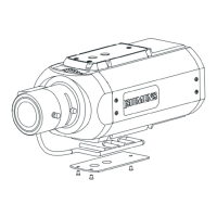
Bezeichnung Tag/Nacht-Kamera
12 V DC/24 V AC
Tag/Nacht-Kamera
90 – 260 V AC
Description Day/Night Camera
12 V DC/24 V AC
Day/Night Camera
90 – 260 V AC
Gewicht 0,45 kg 0,55 kg Weight 0.45 kg 0.55 kg
Zubehör, nicht im Lieferumfang enthalten
Typ PSU230-12 CAPA2410-P
Bestell-Nr. 2GF1800-8BE 2GF1800-8BJ
Bezeichnung Netzteil für 12 V
DC
Netzteil für 24 V
AC
Gewicht 0,12 kg 0,30 kg
Accessories, not included in delivery
Type PSU230-12 CAPA2410-P
Order No. 2GF1800-8BE 2GF1800-8BJ
Description Power supply unit
12 V DC
Power supply unit
for 24 V AC
Weight 0.12 kg 0.30 kg
Lieferumfang
z CCD-Kamera
z C/CS-Montageadapter
z Installationsanleitung
Scope of delivery
z CCD camera
z C/CS-mount adapter
z Installation guide
Installation
Schritt 1: Montage der Kamera
z Montieren Sie die Kamera an einem Wandarm, Deckenarm oder
Schwenkantrieb. Benutzen Sie dazu das ¼-Zoll-Stativgewinde
(3), um ein Verdrehen der Kamera zu verhindern.
z Montieren Sie die Kabelführung an der Kamera, um
sicherzustellen, dass die Kabel sicher an ihrem Platz gehalten
werden (siehe Abb. A).
Schritt 2: Anbringen des Kameraobjektivs
Wählen Sie eine der folgenden Optionen:
z Für C-Mount-Objektive: Bringen Sie einen CS-C-Adapter an der
Kamera an und schrauben Sie das Objektiv dann direkt auf die
Kamera.
z Für CS-Mount-Objektive: Schrauben Sie das Objektiv direkt auf
die Kamera (kein Adapterring erforderlich).
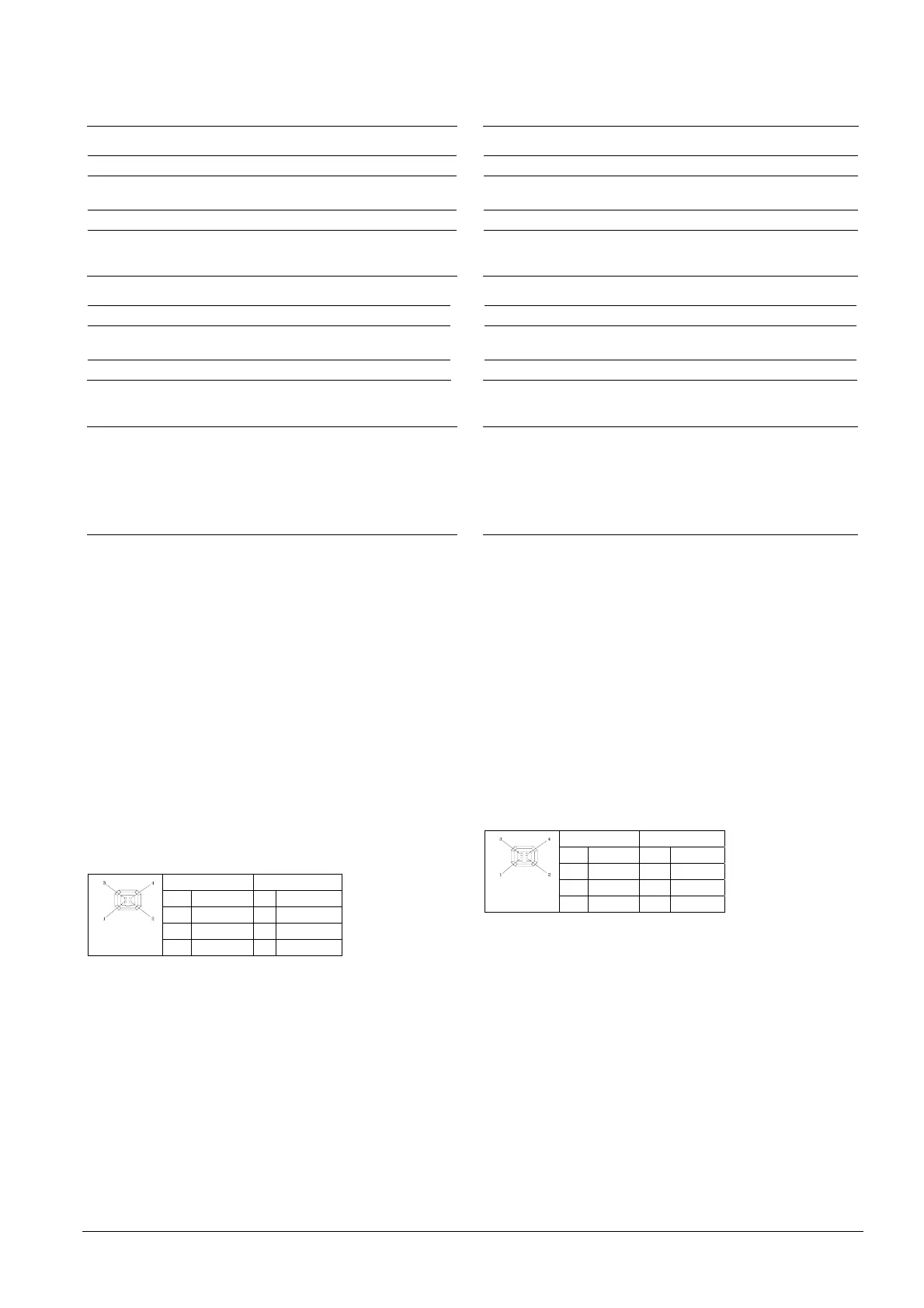
Schritt 3: Anschließen des Objektivs
Für diese Kamera können zwei Arten von Objektiven (DC- oder
videogesteuert) verwendet werden. Wählen Sie jedoch mit dem
Schalter (12) DC oder VIDEO, bevor Sie das Objektiv anschließen,
und achten Sie darauf, dass die Verdrahtung für jeden Objektivtyp
der Stiftbelegung unten entspricht.
Videoobjektiv DC-Objektiv
1 +12 V 1 Damp-
2 NC 2 Damp+
3 VIDEO 3 Drive +
4 Masse 4 Drive-
schließen Sie dann das Steuerkabel am IRIS-Anschluss (4, seitlich
oder hinten) der Kamera an.
Schritt 4: Anschließen des Videosignals
z Für Composite Video: verbinden Sie den BNC-Anschluss
VIDEO OUT (6) über ein Koaxialkabel mit dem Monitor.
z Für TP-Video: Schließen Sie das TP-Kabel am Twisted-Pair-
Videoausgang (9) an. Achten Sie auf die korrekte Polarität. Bei
Benutzung des TP-Ausgangs wird am anderen Ende der TP-
Leitung ein TP-Empfänger wie ein TP-RXI1 oder entsprechend
benötigt. Stellen Sie mit dem DIP-Schalter (8) DIP 1-4 die
Sendereigenschaften ein:
Installation
Step 1: Mounting the camera
z Attach the camera to a wall bracket, ceiling bracket, pan/tilt
mount or other suitable fitting. Use the ¼ inch thread tripod
mount hole (3) to prevent the camera from rotating.
z Mount the cable guide to the camera to ensure that the cables
are kept securely in place (see Fig. A).
Step 2: Fitting the lens to the camera
Select one of the following options:
z For C-mount lens: Add a CS-C adapter to the camera, then
screw the lens directly onto the camera.
z For CS-mount lens: Screw the lens directly onto the camera
(no adapter ring required).
Step 3: Connecting the lens
Two types of lens (DC- or video-controlled) can be used for this
camera. However, select DC or VIDEO lens using the switch (12)
before connecting the lens and make sure the wire connection for
each type of lens is conforming to the pin assignment below.
Video Lens DC Lens
1 +12 V 1 Damp-
2 NC 2 Damp+
3 VIDEO 3 Drive +
4 GND 4 Drive-
Then connect the control cable to the IRIS connector (4, side or
rear) on the camera.
Step 4: Connecting the video signal
z For composite video: Connect BNC connector VIDEO OUT (6) to
the monitor with a coax cable.
z For TP video: Connect TP cable to the twisted pair
video output (9). Ensure correct polarity. Usage of TP output
requires a TP receiver at the other end of the TP line such as TP-
RXI1 or equivalent. Adjust the transmitter characteristics using
DIP SW (8) DIP 1-4:
 Loading...