Installing, connecting up and commissioning
3.2 Installing and commissioning the CM 1243-5
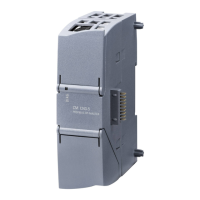
CM 1243-5
Operating Instructions, 04/2011, C79000-G8976-C246-01
21
Procedure for installation and commissioning
NOTICE
Installation location
During installation, make sure that the upper and lower ventilation slits of the module are
not obstructed and good ventilation is possible. Above and below the device, there must be
a clearance of 25 mm to allow air to circulate and prevent overheating.
Remember that the permitted temperature ranges depend on the position of the installed
device.
Device position / permitted temperature range Installation location
Horizontal installation of the DIN rail:
0 °C to 55 °C
Vertical installation of the DIN rail:
0 °C to 45 °C
NOTICE
Connection with power off
Only wire up the S7-1200 with the power turned off.
Power supply from the power outputs of the CPU
The power of the CM must be supplied via the power outputs of the CPU.
Keep within the maximum load of the power outputs of the CPU.
You will find data relating to the current consumption and power loss of the CM in the
section Technical specifications (Page 29).
Groun
ding the PROFIBUS cable
If a CM 1243-5 is plugged into the S7-1200, a PROFIBUS cable must always be connected
to the CM 1243-5. The PROFIBUS cable must be grounded.
 Loading...