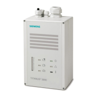
Technical data for the radio gateway FDCW221
8
74 | 82
2015-11-06
8 Specifications
8.1 Technical data for the radio gateway FDCW221
You will find information on approvals, CE marking, and the relevant EU directives
for this device (these devices) in the following document(s); see 'Applicable
documents' chapter:
● Document 010087
Detector line Operating voltage DC 12…33 V
Operating current Typ. 1 mA
Maximum current connection factor 5 + n*1 (n=number of radio detectors)
Quiescent current connection factor 4 + n*1 (n = number of radio devices)
Address connection factor 2 + n*1 (n = number of radio detectors)
Separator connector factor 1
Protocol FDnet
Compatibility See 'List of compatibility'
Design ● Inherently short-circuit-proof
● Protected against polarity reversal
● Protected against overvoltage
Line separator Line voltage:
● Nominal DC 32 V (= V
nom
)
● Minimum DC 12 V (= V
min
)
● Maximum DC 33 V (= V
max
)
Voltage at which the separator opens:
● Minimum DC 7.5 V (= V
SO min
)
● Maximum DC 10.5 V (= V
SO max
)
Permanent current when switches are closed Max. 0.5 A (= I
C max
)
Switching current (e.g., in the event of a short-
circuit)
Max. 1 A (= I
S max
)
Leakage current when switches are open Max. 1 mA (= I
L max
)
Serial impedance when switches are closed Max. 0.5 Ω (= Z
C max
)
Radio
Number of radio gateways with radio cell
overlapping
Max. 16
Number of radio detectors per radio gateway Max. 30
Sending/receiving aerials 2 (aerial diversity)
Radio transmission:
● Frequency range 868…870 MHz, SRD band (Short Range Device)
● Channel grid 25 kHz
● Number of channels 80
● Transmitting power <5 mW ERP
● Range:
– In building Max. 40 m
– Outdoors Max. 200 m
● Damping Max. 90 dB

 Loading...