To lock the board
(2)
Slide the board into the system using its guide rails. Insert the hooks on the
locking levers into the recesses in the shelf. Press down on both levers
simultaneously in the direction of the shelf until they click into place.
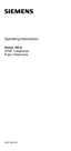
Locking and unlocking boards
Figure 4-23 Locking and unlocking boards
Special board attachments
The power supply unit is screwed onto the grill of the relevant cabinet.
The REAL special board is mounted on the metal back panel (basic cabinet only) and connected to the
backplane with a ribbon cable.
4.1.13 Connecting terminals
See Chapter 9 for information on connecting terminals.
4.1.14 Performing a visual inspection
Introduction
A visual inspection of the hardware, cables and the power supply is to be performed before the system
is started up. The procedures are displayed in Table 4-4. The visual inspection must be performed
when the system is in a de-energised state.
Caution
It is important to ensure that the system is earthed and disconnected from the power supply
before beginning work
The measures for protecting electrostatically sensitive devices must be observed (see page
1-5).
Visual inspection procedures
Table 4-4 Visual inspection procedures
http://cmweb01.mch.pn.siemens.de/e_doku/en/h150/h15/30/sh/2/15_4m.htm (26 of 27) [06/04/2000 13:04:42]

 Loading...