Step Activity Tool/
remarks
Action
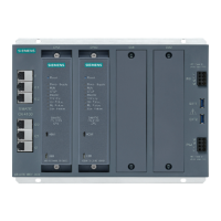
1. Compare the slots for the
existing boards with the
component mounting
diagram.
Component mounting diagram
for boards.
Correct the board configuration
and notify the appropriate sales
department.
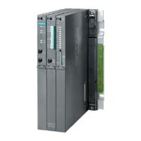
2. Check all boards to see if
they are firmly seated.
See page 4-33
Check the additional
mechanical attachments for
the PSUI.
Reconnect and fasten the boards.
3. Check the local mains
voltage.
Digital multimeter.
You can begin to start-up Hicom 150 E OfficePro as described in Section 5.1 once the visual
inspection has been performed.
| Siemens | Home | First Page | Previous Page | Next Page | Search | Info | Help |
© Siemens AG, München, 1998
Hicom 150 E Office Rel.1.0 Service Manual, 2, 1998-06-26
Siemens Part No.: P31003-M1530-X403-2-7620
Conversion Date: 1998-09-18
http://cmweb01.mch.pn.siemens.de/e_doku/en/h150/h15/30/sh/2/15_4m.htm (27 of 27) [06/04/2000 13:04:42]

 Loading...
