Table 5-12 Country codes
Table 5-13 Entering the route telephone number
Table 6-1 Start-up rules for removing/inserting boards
Table 6-2 P 500 printer - DIP switch series 1
Table 6-3 P 500 printer - DIP switch series 1, switches 1-1 to 1-3
Table 6-4 P 500 printer - DIP switch series 2
Table 6-5 Upgrading Hicom 150 E OfficeCom/OfficePoint hardware
Table 7-1 Compressed output format - explanation of output fields
Table 7-2 Long output format - explanation of output fields
Table 9-1 AT command sets for the optiset E control adapter in API1 mode
Table 9-2 AT command sets for the optiset E data adapter
Table 9-3 V.25bis commands for the optiset E data adapter
Table 9-4 Pin assignments of the plug-type AC adapter
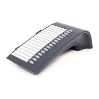
Table 9-5 Headsets for the optiset E adapter
Table 9-6 optiset E for Hicom 150 E Office - maximum number of optiset E adapters
Table 9-7 optiset E for Hicom 150 E Office - possible configurations
Table 10-1 ET/A contact assignment
Table 11-1 Hicom 150 E Office - Plus products, applications
Table 12-1 Tools / aids for mounting the base station
Table 12-2 Hicom cordless 150 E - prohibited adjacent base stations
Table 12-3 Insertion loss values (ae)/range loss for radio area
Table 12-4 Insertion loss values (ae)/range loss for the radio area
Table 12-5 Difference in length between various cable types
Table 13-1 H1 (CBMOD) / H9 (CBFC) LEDs - indicator status of the central board
Table 13-2 H2 (CBMOD) / H10 (CBFC) LEDs - indicator status of the integrated modem
Table 13-3 LED indicators for peripheral boards
Table 13-4 LED indicators on the CBFC
Table 13-5 LED indicators on the EXTEB:
Table 13-6 Telephone test
Table 13-7 Error class 09 - hardware errors
Table 13-8 Error class 15 - APS
Table 13-9 Error class 16 - general errors
Table 13-10 Error class 20 - call processing
Table 13-11 Error class 21 - device handler
Table 13-12 Error class 26 - presence
http://cmweb01.mch.pn.siemens.de/e_doku/en/h150/h15/30/sh/2/h150_eha.htm (3 of 4) [06/04/2000 13:02:18]
 Loading...
