103
LOGO! manual
EWA 4NEB 712 6006-02
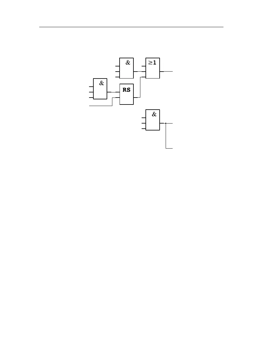
Functional diagram of the LOGO! solution
The block diagram for controlling the dereeler with LOGO! is as follows:
I2
I4
I5
R
I1
I3
x
x
I6
I2
I4
x
S
Manual mode on
Manual dereeler control Dereeler drive on
Automatic mode on
Punching device off
Strip taut
Strip loose
Indicator light for
automatic mode
Enable punching
device
Automatic mode on
Punching device off
Q1
Q2
Q3
5.7.4 Advantages of the LOGO! solution
If you use LOGO!, you need fewer switching devices less wiring is in-
volved. You also save on assembly time and space in the switch box. You
may even be able to use a smaller switch box.
Applications
 Loading...

