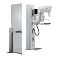
Siemens AG SPB7-250.844.01 Page 1 of 10 MAMMOMAT
Novation
DR
Medical Solutions Rev. 03 08.04 CS SD 24 Wiring Diagrams
X041E 4-1
MAINS VOLTAGE CONNECTION 0
The mains input can be either 1-phase or 2-phase, 50 or 60 Hz.
Electrical power to mains input:
0
Mains voltage 1-phase: 208, 230, 240 and 277 V ±10%
or
2-phase: 208, 230, 240, 277 and 400 V ±10%
Mains Frequency: 50 or 60 Hz
Maximum load: 10kVA (momentary) and 0.8 kVA (long time load).
Fuse: 25 A (external) 208 -> 400 V.
Power line impedance: 0
The generator section of the mammomat requires a line impedance not exceeding the
maximum values according to the table below:
Connections: 0
Fig. 1
Nominal input voltage [VAC] Ri
max
[Ω]
208 0.45
230 0.50
240 0.60
277 0.65
400 0.85
Power system Type of
connection
Power voltage Power
connections
Singel phase Phase to neutral 208 V-277 V Connect to 3 and 4
Two phase Phase to phase 208 V-400 V
phase to phase.
Note: Max 277 V
phase to neutral/
ground allowed.
Connect to 3 and 4.
Use two phases (of three) in a
normal power distribution sys-
tem.The left over wires, neutral
and the third phase may be con-
nected to terminal 1 and 2. See
Fig. 1.
PE 1 2 3 4
X707
NOV00123
Note 1. PE = Protective Earth
Note 2. Terminals 1 and 2 are not connected internally. Can be used to secure wires when four or five
wire power system is used.

 Loading...

