Description
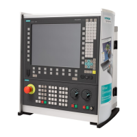
3.4 Operator control and display elements
NCU 7x0.3 PN
Manual, 09/2011, 6FC5397-1EP40-0BA0
25
3.4.4 RESET button
Arrangement
The RESET button is located behind the blanking cover.
Performing a reset operation
The reset operation resets the NCU and forces a new power-up. It is similar to a "Power On
Reset" except that the 24 V power supply does not have to be switched off.
3.4.5 Start-up and mode selector switch
Layout
The Control Unit has two coding switches in the lower section of the front panel.
● The upper switch (labeled SVC/NCK) is the NCK commissioning switch.
Setting during normal operation: "0"
● The lower switch (labeled PLC) is the PLC mode selector switch.
Setting during normal operation: "0"
3/&PRGHVHOHFWRUVZLWFK
1&.FRPPLVVLRQLQJVZLWFK
Figure 3-5 Startup and mode selector switch
Additional references
CNC Commissioning Manual Part 1 (NCK, PLC, drive)
 Loading...