1
Model PAD-5-CLSA
Wiring and Configuring the PAD-5-CLSA
10
Siemens Industry, Inc. A6V101030359_en--_c
Building Technologies Division
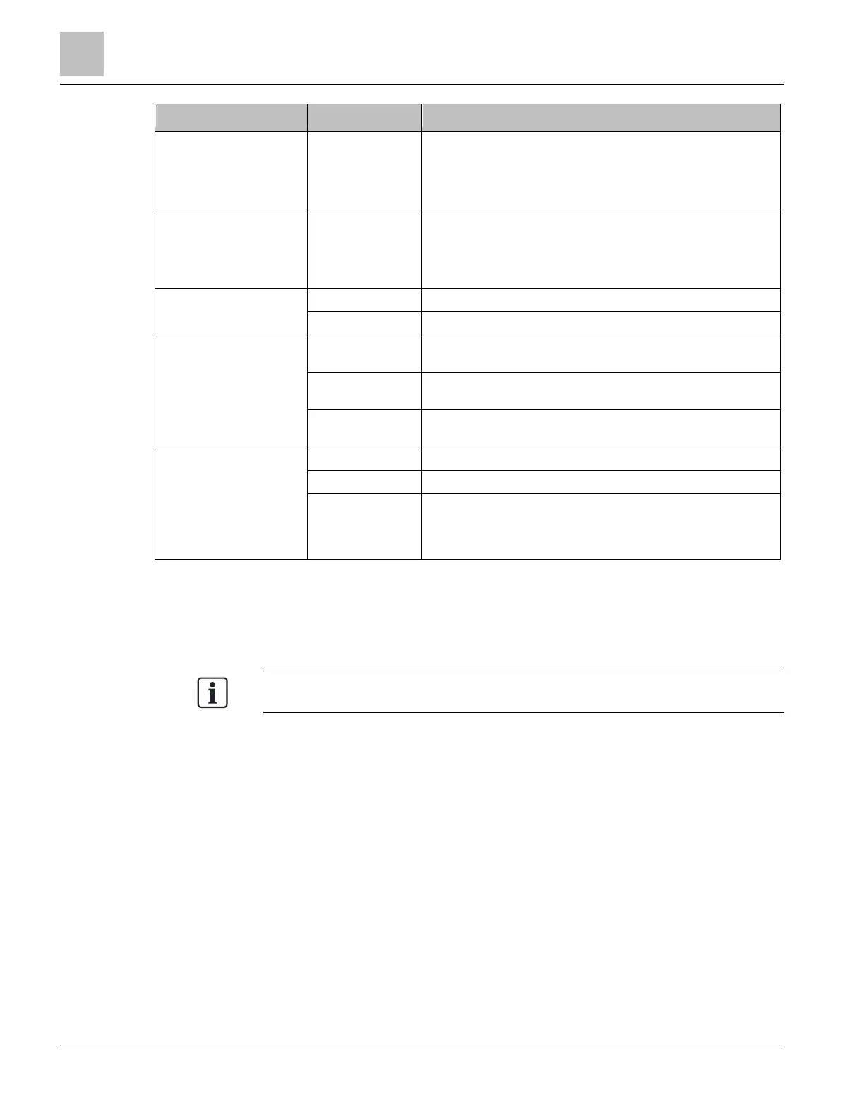
Element Des. Function
Indicators H200
H202
H201
H203
NAC 5 STATUS
NAC 6 STATUS
NAC 7 STATUS
NAC 8 STATUS
Programming X501, X502
X200
X205
X505
DPU Address Programming Holes
Serial Debug/Firmware Programming Port Main processor
Serial Debug/Firmware Programming Port Main processor
Serial Debug/Firmware Programming Port P2 processor
Adjustment elements S202 Reset switch for Main Board processor
S203 Reset switch for NAC Status LEDs
Jumpers X206
Boot Strap Loader Enable/Disable Main processor. Run time
jumper position DIS (2,3)
X504 Boot Strap Loader Enable/Disable P2 processor. Run time
jumper position DIS (2,3)
X203 Main processor Watchdog Enable/Disable. Run time jumper
position EN (1,2)
Connector X300 NAC5,6 output
X400 NAC7,8 output
X102, X103
(bottom of the
board, not shown
in Figure 4)
Expansion board connection
Do not connect AC or batteries until all jumpers and boards are configured and
connected in the system. Once everything is installed and connected, first AC, then
the batteries must be connected.
To power down the system, first disconnect the batteries and then the AC.
 Loading...