Technical specifications
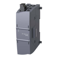
A.18 S7-1200 Potentiometer module
S7-1200 Programmable controller
980 System Manual, 03/2014, A5E02486680-AG
CPU 1217C Simulator (6ES7 274-1XK30-0XA0)
24 VDC sensor
S7-1200 Potentiometer module
The S7-1200 Potentiometer module is an accessory for S7-1200 CPU. Each potentiometer
creates an output voltage proportional to the position of the potentiometer to drive each of
the two CPU analog inputs 0 VDC to 10 VDC. To install the potentiometer:
1. Insert the circuit board ‘fingers’ into any S7-1200 CPU analog input terminal block, and
connect an external DC power supply to the 2-position connector on the potentiometer
module.
2. Use a small screwdriver to make the adjustments: turn the potentiometer clockwise (to
the right) to increase the voltage output, and counterclockwise (to the left) to decrease
the voltage output.
Note
Follow ESD guidelines when handling the S7
-1200 Potentiometer module.
Dimensions W x H x D (mm)
User-supplied voltage input at 2-position connector
1
(Class 2, Limited Power, or sensor power from PLC)
16.4 VDC to 28.8 VDC
Cable length (meters)/type
<30 m, shielded twisted pair
Input current consumption
Potentiometer voltage output to S7-1200 CPU analog
1
0 VDC to 10.5 VDC min.

 Loading...


