Manual for installation of the Sensformer® Connectivity Device
© 2020 Siemens Energy Page 13
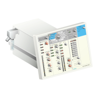
Figure 14 - Set analog sensors
In the standard configuration the Sensformer Connectivity Device
collects the following signals:
• Top oil temperature
(for liquid immersed transformers)
• Winding temperature
(for cast resin transformers)
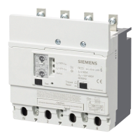
• LV winding current
(for liquid immersed and cast resin transformers)
• Minimum oil level signal
(for liquid immersed transformers)
The default sensor connections are the following:
Improper settings cause false measurement results! Setting the
wrong type value may cause the device to malfunction!
 Loading...