Manual for installation of the Sensformer® Connectivity Device
© 2020 Siemens Energy Page 20
4.1. General
Operating ambient
temperature
0 - 80% relative, non-condensing (31°C
or lower) linearly decreasing to 50% at
40°C
Table 2 - Physical parameters
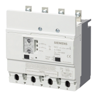
Figure 27 - Sensformer Connectivity Device
Ethernet (10 Mbit / 100 Mbit)
mini USB 2.0 (not used)
RS485 (ModBus)
3 x Analog input:
4-20mA DC
(active or passive) or
±20mApp AC (passive)
2 x Digital input
1 x PT100 input (3-wire)
1 for mobile communication
(SMA female)
1 for GPS (SMA female)
Table 3 - Common specifications
4.2. Power supply
100 – 240 VAC (50Hz/60Hz) */***
AC:
L: line, N: Neutral, PE: Protective
Earth
Table 4 – Parameters of power supply
*Remark: The device is able to work on 120 - 240 VDC, but it is
not certified to such power input.
**Remark: Take into consideration chapter 2.1.2.1. paragraph 8.
(Connect the power supply) on page 11.
***Remark: Mains supply voltage fluctuations not to exceed ± 10
percent of the nominal voltage.
4.3. Analog inputs
4-20mA DC (active or passive)
or ±20mApp AC (passive)
Independent in ±20mA mode,
Polarity sensitive in 4-20 mA mode.
120 Ohm (4-20mA mode) or
80 Ohm (±20 mA mode)
120 mA (sum of all ports)
Table 5 – Parameters of analog inputs
 Loading...