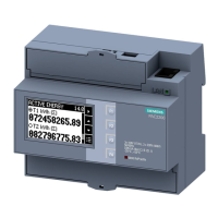
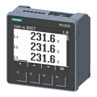
Description
2.1 Performance features
PAC2200
14 Equipment Manual, 12/2019, L1V30415167B-03
Display and operator control
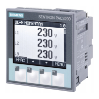
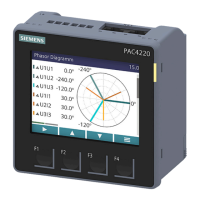
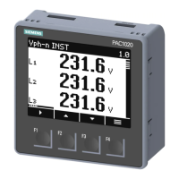
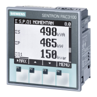
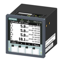
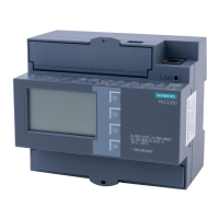
● LC display
● Four control keys with variable function assignment
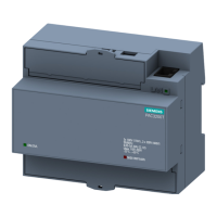
● LED for Ethernet communication, active energy pulse indicator
● powerconfig from version 3.7.
● powermanager from version 3.4.
● Web server (HTTP) (optional)
Interfaces
● Ethernet (optional)
● RS485 interface (optional)
● M-BUS (optional)
● Digital input
● Digital output
Memory
● Adjusted device parameters are permanently stored in the device memory.
● Extreme values (maximum or minimum) are permanently stored in the internal device
memory. Values can be reset via powerconfig, Modbus command or directly on the
device via the menu.
Response in the case of power failure and power restore
After a power failure, the device starts back at zero with the calculation of the average power
demand of the
total active power and total reactive power.
Counter statuses and extreme values are written from the volatile to the
non-volatile memory at the following intervals:
Counter values Every 5 mins.
Extreme values Every 5 secs., if available
 Loading...
