Installation
5.4 Installation steps
SENTRON PAC3200
Manual, 02/2008, A5E01168664B-04
69
5. Clamp the device to the switching panel with the two brackets provided (Fig. "Installation
step B"). To do this, proceed as follows:
– Hold the device firmly with one hand
– Hang the brackets onto the left and right sides of the housing.
To do so, insert the lugs of the bracket (2) into the slot on the housing (1).
– Tighten the locking hook.
To do so, place your index finger and middle finger on the support arms as shown in
the Fig. "Installation step C" and engage the locking hook with your thumb.
The engage mechanism of both brackets enables the installation engineer to secure
the device in the switching panel quickly and without tools.
If a higher level of protection is desired, the pressure can be increased evenly on all
sides with the help of the four screws of the brackets.
6. Tighten the 4 screws evenly in the two brackets; tightening torque 0.025 to 0.03 Nm (Fig.
"Installation step D"). The front of the switching panel is fully sealed with the standard,
integrally extruded seal.
7. When using the Ethernet interface:
– Ensure strain relief for the RJ45 connector.
Secure the Ethernet cable to the panel for this purpose. Fix the cable in position as
shown in the Fig. "Installation - E" at location (3) using a self-adhesive cable clamp or
other suitable small installation accessory.
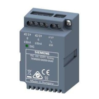
8. An optional expansion module can be connected. You can find the installation
instructions in the operating instructions of the expansion module.
Installation is complete.
NOTICE
Ensure that no tools or other potentially hazardous objects have been left at the installation
location.

 Loading...
