•
Insert the device into the assembly opening until it hits the limit and keep holding it tightly.
•
Attach the 2 mounting elements (included with the device) on both sides of the case. You have the possi-
bility to attach the mounting elements as follows:
[dw_assembly, 1, en_US]
Figure 9-2
Attaching the Mounting Elements
(1) Mounting plate
(2) Mounting element
•
Swing the mounting element over the rear cone to the position.
•
Use a screw driver (0.6 mm x 4.5 mm) to fix the mounting elements until the slipping clutch takes effect.
NOTE
The mounting instructions must be performed correctly to provide sufficient protection against touching
live parts.
UL-Certification Conditions
Field wires of control circuits can be separated from other circuits with respect to the end-use requirements.
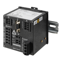
Assembly: Devices without Display for DIN Rail Mounting
NOTE
The DIN rail must be mounted horizontally.
To mount the device on a DIN rail, proceed as follows:
Commissioning and First Steps
9.3 Assembly
SICAM, SICAM P850/P855 7KG85X, Manual 193
E50417-H1040-C482-A9, Edition 03.2022

 Loading...


