Supply from a Direct Voltage Source
Terminal N/-: Negative supply voltage
Terminal L/+: Positive supply voltage
Terminal Earthing: Protective grounding terminal
NOTE
Always connect the grounding at the device to the terminal for the protective phase grounding (terminal
block H).
Terminals and Conductors
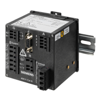
The device has the following terminal blocks:
Terminal Block Description
E 3 inputs for alternating current measurement
F 4 inputs for alternating voltage measurement
H Supply voltage
G 2 binary outputs
Terminals for supply voltage (H), inputs for current measurement (E), inputs for voltage measurement (F), and
binary outputs (G):
•
Conductor cross-section, rigid max.: 2.5 mm
2
(AWG 14)
•
Conductor cross-section (conductor with ferrule): 1.5 mm
2
(AWG 16)
•
Conductor cross-section (conductor with ferrule, terminal F): 2.5 mm
2
(AWG 14)
•
Tightening torque: 0.4 Nm to 0.5 Nm (3.5 in-lb to 4.5 in-lb)
•
RS485 interface (J) on the terminal side: RS485 cable with 9-pole D-sub socket
•
Ethernet interface (Z) on the top side: Ethernet patch cable or crossover cable
Functions of the Terminals
Terminal
Assigned Function,
Measured Value or Indi-
cation
Description
E: I
A
L1
⇒
Ia Phase a, input, current measurement
E: I
A
L1
⇐
Ia Phase a, output, current measurement
E: I
B
L2
⇒
Ib Phase b, input, current measurement
E: I
B
L2
⇐
Ib Phase b, output, current measurement
E: I
C
L3
⇒
Ic Phase c, input, current measurement
E: I
C
L3
⇐
Ic Phase c, output, current measurement
F:
A
L1
Van Phase a, voltage measurement
F:
B
L2
Vbn Phase b, voltage measurement
F:
C
L3
Vcn Phase c, voltage measurement
F: N N Neutral phase, voltage measurement
G: 1 Binary output 1 Binary output 1
G: 2 Root Common root for both binary outputs
G: 3 Binary output 2 Binary output 2
H (Earth) Protective phase –
Commissioning and First Steps
9.5 Electrical Connection
SICAM, SICAM P850/P855 7KG85X, Manual 197
E50417-H1040-C482-A9, Edition 03.2022

 Loading...


