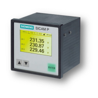
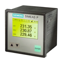
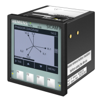
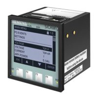
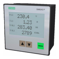
Measured Values Measuring Path
1
Menu Tolerances
2
Voltage L1-N, L2-N, L3-N
±0.2 %
Voltage
L1-L2, L2-L3, L3-L1, Σ
3
±0.2 %
Current
L1, L2, L3, N, Σ
3
±0.2 %
Active power P
+ demand, - supply
L1, L2, L3, Σ
±0.5 %
Reactive power Q
+ cap, - ind
L1, L2, L3, Σ ±0.5 %
Apparent power S
L1, L2, L3, Σ
±0.5 %
Power factor |cosϕ|
4
L1, L2, L3, Σ
±0.5 %
Active power factor cosϕ
4
L1, L2, L3, Σ ±0.5 %
Phase angle
4
L1, L2, L3, Σ ±2°
System frequency
5
L1-N ±10 mHz
Active energy demand
L1, L2, L3, Σ
±0.5 %
Active energy supply
L1, L2, L3, Σ
±0.5 %
Active energy total
L1, L2, L3, Σ
±0.5 %
Active energy net demand
Σ
±0.5 %
Reactive energy cap
L1, L2, L3, Σ
±0.5 %
Reactive energy ind L1, L2, L3, Σ ±0.5 %
Reactive energy total L1, L2, L3, Σ ±0.5 %
Apparent energy L1, L2, L3, Σ ±0.5 %
Unbalance voltage Four-wire system
±0.5 %
Unbalance current Four-wire system
±0.5 %
THD voltage L1, L2, L3
±0.5 %
THD current L1, L2, L3
±0.5 %
Harmonic voltage
5., 7., 11., 13., 17. and 19. H.
L1, L2, L3 ±0.5 %
Harmonic current
5., 7., 11., 13., 17. and 19. H.
L1, L2, L3 ±0.5 %
Limit violation Counter 1 to 4
Analog input
6
external
±0.5 %
Binary input
6
external
 Loading...
