The default values of the parameters p4700, p4701, p4702 correspond to the settings for TZW3,
TZW4, TZW5 in FW versions < V1.09.
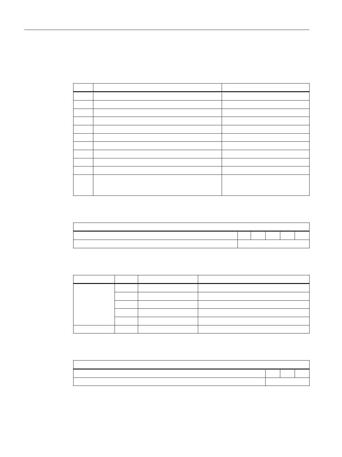
Table A-38 Value selection for TZW3, TZW4, TZW5
Value Description Format
0 D-IN Data structure see table A-40
1 D-OUT Data structure see table A-41
2 Button Data structure see table A-43
3 Door position in mm 16-bit unsigned integer
4 Door setpoint speed in mm/s 16-bit unsigned integer
5 Door actual speed in mm/s 16-bit unsigned integer
6 Motor current in mA 16-bit signed integer
7 Motor current limitation in mA 16-bit signed integer
8 Voltage of the motor output stage in V 16-bit unsigned integer
9 Remaining power capacity of the braking resistor in J 16-bit signed integer
10 As of V1.12: Operating status display ASCII value of the currently displayed
operating status (see section Operat‐
ing status display (Page 303))
Table A-39 TZW data structure for value "D-IN"
TZW3, TZW4, TZW5
15 - 5 4 3 2 1 0
Reserved D-IN
Table A-40 Bits "D-IN"
Group Bit Meaning Remarks
D-IN 0 Input 4 X6, INPUT 4
1 Input 3 X6, INPUT 3
2 Input 2 X6, INPUT 2
3 Input 1 X6, INPUT 1
4 Input 0 X5, INPUT 0
5 - 15 Reserved
Table A-41 Data structure for value "D-OUT"
TZW3, TZW4, TZW5
15 - 3 2 1 0
Reserved D-OUT
Appendices
A.1 Structure of user data/process data
ATD4xxW for industrial applications
328 System Manual, 06/2022, A5E51901827B AA

 Loading...


