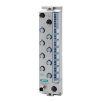
Communication module CM 8x IO-Link + DI 4x24VDC M12-L (6ES7148-6JG00-0BB0
Equipment Manual, 09/2020, A5E49284833-AA
17
3.1 Terminal and block diagram
The following figure shows an example of the pin assignment for Port Class A and Port Class
B.
Bus interface with integrated 2-port switch
Supply voltage 1L+ (non-switched)
Load voltage 2L+ (switched)
IO-Link device, class A and 1x switch
LED LINK Port 1/Port 2 (green)
IO-Link Port Class A + DI
RUN/network status LED (green)
ERROR/module status LED (red)
Infeed of supply voltages
MAINT/IO status LED (yellow)
Loop-through of supply voltages

 Loading...


