Interrupts/diagnostics alarms
5.1 Status and error displays
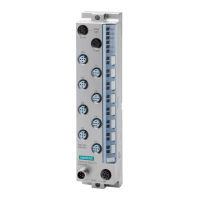
Communication module CM 8x IO-Link + DI 4x24VDC M12-L (6ES7148-6JG00-0BB0
28 Equipment Manual, 09/2020, A5E49284833-AA
Meaning of the LEDs
The following tables set out the meaning of the status and error displays.
Behavior of the LEDs RN/NS (RUN/network status), ER/MS (ERROR/module status) and MT/IO
(MAINT/IO status)
Table 5- 1 Error display of the LED
Meaning Remedy
RN/NS
ERR/MS
MT/IO
No or insufficient supply volt-
age
Check the supply voltage.
On (green)
On (red)
On (yellow)
Test of LEDs during startup:
The three LEDs light up simul-
taneously for approximately
The three LEDs light up simul-
taneously for approximately
2 s while "Reset to factory
Flashes
off
Off
Activate the ET 200eco PN
with the configuration soft-
ware or via the user pro-
Configure the ET 200eco PN
via the configuration soft-
Parameters are assigned to
module
Loading firmware (when the
firmware update is performed
during startup, all LEDs retain
On (green)
vant
vant
The ET 200eco PN is currently
exchanging data with the IO
vant
Flashes
vant
Module diagnostics is availa-
ble
Evaluate the diagnostics and
eliminate the error.
The preset configuration does
not match the actual configu-
Check the configuration of
the ET 200eco PN.
Correct the errors in the
parameter assignment.

 Loading...


