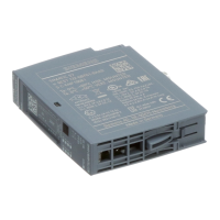
Interface module IM 155-6 PN/2 HF (6ES7155-6AU01-0CN0)
Manual, 10/2018, A5E03915895-AH
5
Preface ................................................................................................................................................... 3
1 Guide ...................................................................................................................................................... 7
2 Product overview .................................................................................................................................. 12
2.1 Properties ................................................................................................................................ 12
2.2 Functions ................................................................................................................................ 16
2.2.1 Device replacement ................................................................................................................ 20
2.2.2 Real-time communication ....................................................................................................... 21
2.2.3 Isochronous real-time communication .................................................................................... 21
2.2.4 Prioritized startup .................................................................................................................... 22
2.2.5 Submodules ............................................................................................................................ 22
2.2.6 Media redundancy (MRP) ....................................................................................................... 23
2.2.7 Shared device ......................................................................................................................... 23
2.2.8 Isochronous mode .................................................................................................................. 24
2.2.9 Module-internal Shared Input/Shared Output (MSI/MSO) ...................................................... 24
2.2.10 System redundancy S2 ........................................................................................................... 25
2.2.11 Alternating IO devices during operation ("docking systems") ................................................. 25
2.2.12 Oversampling .......................................................................................................................... 25
2.2.13 Value status ............................................................................................................................ 26
2.2.14 PROFIenergy .......................................................................................................................... 26
2.2.15 Configuration control (option handling) ................................................................................... 27
2.2.16 Use of fail-safe modules ......................................................................................................... 27
2.2.17 Multi Hot Swap ........................................................................................................................ 27
2.2.18 Module-to-Module Communication (MtM) .............................................................................. 28
2.2.19 Setting the time ....................................................................................................................... 29
3 Wiring ................................................................................................................................................... 30
3.1 Pin assignment ....................................................................................................................... 30
3.2 Block diagram ......................................................................................................................... 31
4 Parameters/address space ................................................................................................................... 32
4.1 Parameters ............................................................................................................................. 32
4.2 Explanation of parameters ...................................................................................................... 32
4.2.1 Enable configuration control ................................................................................................... 32
4.2.2 Diagnostics (maintenance) undervoltage ............................................................................... 33
4.3 Substitute value behavior ....................................................................................................... 33
4.4 Status of the supply voltage L+ of the I/O modules ................................................................ 34

 Loading...


