EasyManuals Logo

Siemens SIMATIC NET S7-300 User Manual

Siemens SIMATIC NET S7-300
317 pages
To Next Page IconTo Next Page
To Previous Page IconTo Previous Page
Page #219 background imageLoading...
Page #219 background image
7 Programming FCs (Functions) and FBs for S7 Ethernet CPs
A-219
S7-CPs for Industrial Ethernet Configuring and Commissioning
Release 01/2007
C79000-G8976-C182-07
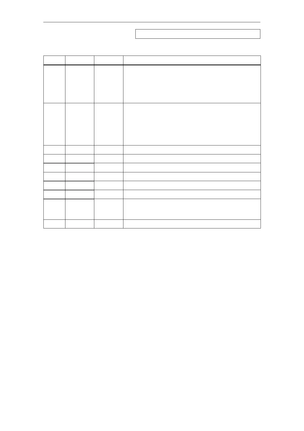
Table 7-6 AG_CNTRL Codes
DONE MeaningSTATUSERROR
0 1
8189
H
The CP version / firmware used does not support FC10.
The code is set when you call a CP 3431-EX20 with firmware as
of V1.3.9; with other CP types, the code 80B0
H
is set instead.
Note: FC10 in version V1.0 is supported by the CPs as of
CP 343-1 EX21/GX21; this code does not occur with these
modules.
0 1
8090
H
No module with this module base address exists.
or
The FC used does not match the system family being used
(different FCs must be used for S7 -300 and S7-400).
or
The function is not supported by this module.
0 1
8091
H
The module base address is not on a double-word boundary.
0 1
80B0
H
The module does not recognize the data record.
0 1
80C0
H
The data record cannot be read.
0 1
80C1
H
The specified data record is currently being processed.
0 1
80C2
H
There are too many jobs pending.
0 1
80C3
H
CPU resources (memory) occupied.
0 1
80C4
H
Communication error
The error occurs temporarily; it is usually best to repeat the job in
the user program.
0 1
80D2
H
The module base address is incorrect.
FC10 AG_CNTRL - continued

Table of Contents

Other manuals for Siemens SIMATIC NET S7-300

Questions and Answers:

Question and Answer IconNeed help?

Do you have a question about the Siemens SIMATIC NET S7-300 and is the answer not in the manual?

Siemens SIMATIC NET S7-300 Specifications

General IconGeneral
Product Type DesignationSIMATIC NET S7-300
MountingDIN rail mounting
Protection ClassIP20
CPU ModelsVarious models available (e.g., CPU 312, CPU 314)
Communication InterfacesMPI, PROFIBUS DP
Power Supply24 V DC power supply required. Different power supply modules available.
I/O ModulesDigital input modules, digital output modules, analog input modules, analog output modules
ProgrammingSTEP 7 software
Supply Voltage24V DC or 120/230V AC (depending on model)
Digital InputsAvailable via digital input modules
Digital OutputsAvailable via digital output modules
Analog InputsAvailable via analog input modules
Analog OutputsAvailable via analog output modules
Communication FunctionsMPI, PROFIBUS DP, Ethernet (depending on model)
ProtocolsMPI, PROFIBUS DP, TCP/IP (depending on model)
Operating Temperature0°C to 60°C
Storage Temperature70 °C
MemoryDepends on CPU model (e.g., 32 KB to 1.5 MB)

Related product manuals