Safety Integrated Functions in
SINAMICS Drive Systems
6.5 Behavior and reactions in the user program
Connection of the SINAMICS S120 to the Technology CPU
Product Information, 09/2011, A5E00480378-04
199
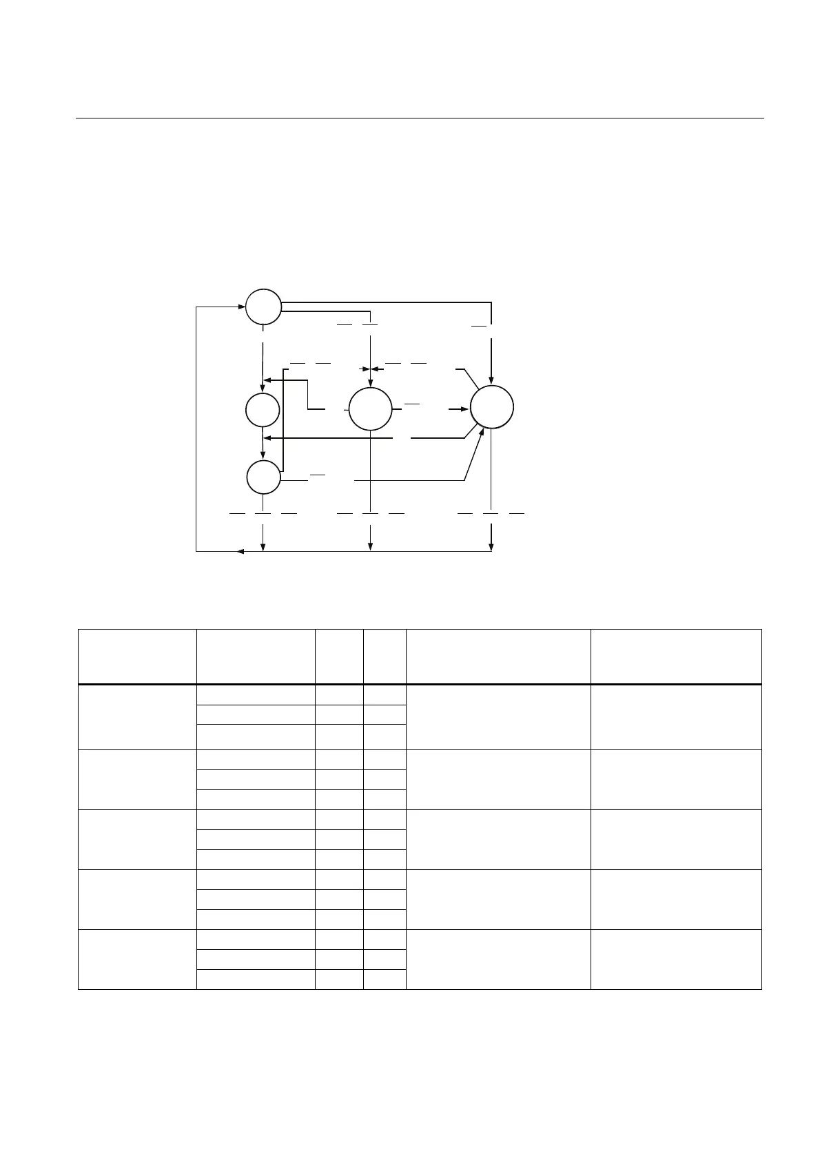
Reaction in the user program to select or deselect the SS2, SOS and SLS safety extended functions
For the SS2, SOS, and SLS status transitions, an appropriate response for the technology
object needs to be programmed in the user program to fulfill the monitored safety-related
conditions in the drive (e.g. maximum velocity, standstill). The user program can detect
status transitions by cyclically processing the StatuswordSafety variable in the TO DB
of the axis.
66Ȓ626Ȓ6/6
66Ȓ626
66Ȓ626Ȓ6/6 66Ȓ626Ȓ6/6
66
66
66
66Ȓ626
66Ȓ626
66Ȓ626Ȓ6/6
66Ȓ626Ȓ6/6
66Ȓ626Ȓ6/6
66B626
,'/(
66B$&7,9(
6/6B6(/(&7('
626B6(/(&7('
Figure 6-2 Status diagram
Table 6- 3 States of the SS2, SOS and SLS safety-related functions
Status StatuswordSafety Value Addr.
in TO
DB
Drive response Response in the user
program
SS2_Active 0 140.2
SOS_Selected 0 140.3
SLS_SELECTED
SLS_Deselected 0 140.4
Drive monitored for the
maximum permissible velocity
after expiration of the delay
time
Limit velocity setpoint
SS2_Active 1 140.2
SOS_Selected 0 140.3
SS2_ACTIVE
SLS_Deselected X 140.4
Drive brakes independently and
after the delay time switches to
SS2_SOS
None
Automatic follow-up mode
SS2_Active 1 140.2
SOS_Selected 1 140.3
SS2_SOS
SLS_Deselected X 140.4
Monitoring of the operational
stop
Keep in standstill
SS2_Active 0 140.2
SOS_Selected 1 140.3
SOS_SELECTED
SLS_Deselected x 140.4
Drive monitors the operational
stop after expiration of the
delay time
Bring to a standstill and
remain in this state
SS2_Active 0 140.2
SOS_Selected 0 140.3
IDLE
SLS_Deselected 1 140.4
The SLS, SS2 and SOS
safety-related functions are not
active
No restrictions on the axis
because of a safety-related
function
XNot relevant

 Loading...


