Configuration
5.3 Examples
1FN3 linear motors
132 Configuration Manual, 10/2018, 6SN1197-0AB86-0BP2
Dimensioning the cooling system
5.3.3.1
Basic information
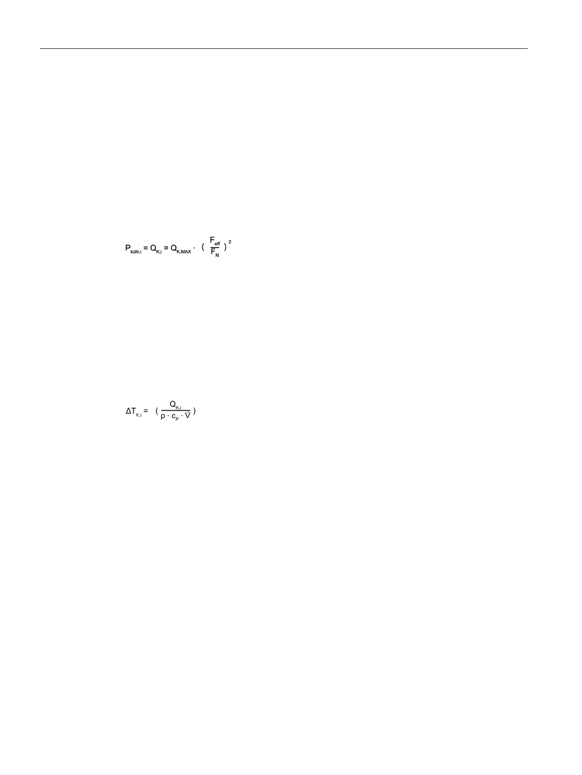
Individual coolers
Based on the required effective force of the duty cycle F
eff
, heat Q
K,i
that must be dissipated
by the individual coolers can be calculated first of all. This also corresponds to the cooling
capacity P
kühl,i
, which a cooling unit or a heat exchanger must have for the cooling being
considered.
The values for rated force F
N
and heat Q
K,MAX
to be dissipated under full load conditions is
obtained from the data sheets.
The volume flow rate is defined; however, the value that is specified in the data sheet tables
should be used.
The pressure drop associated with the volume flow rate can be taken from the
characteristics for the primary section main cooler as well as for the primary section
precision cooler and secondary section cooling.
Temperature rise ΔT
K,i
between the flow and return for the individual coolers can be
determined for a given volume flow rate
Variables ρ and c
ρ
designate the density or the specific thermal capacity of water as coolant:
ρ = 998 kg/m
3
, c
ρ
= 4180 J/(kg·K).
Connecting coolers in series
For cooling circuits connected in series, the greatest volume flow rate that results for the
individual coolers is the determining value for the entire system:
V
gesamt
= max(V
1
, V
2
, V
3
, …)
Calculate the individual pressure drops and temperature rises. Calculate the sum for the
pressure drop Δp
gesamt
and the temperature rise ΔT
gesamt
in each case:
Δp
gesamt
= Δp
K,1
+ Δp
K,2
+ Δp
K,3
+…
ΔT
gesamt
= ΔT
K,1
+ ΔT
K,2
+ ΔT
K,3
+…
If you are using one cooling unit or heat exchanger for all cooling circuits together, the
necessary cooling capacity P
kühl
is calculated from the individual cooling capacities P
kühl
as
follows:
P
kühl
= P
kühl,1
+ P
kühl,2
+ P
kühl,3
+… = Q
K,1
+ Q
K,2
+ Q
K,3
+…

 Loading...


