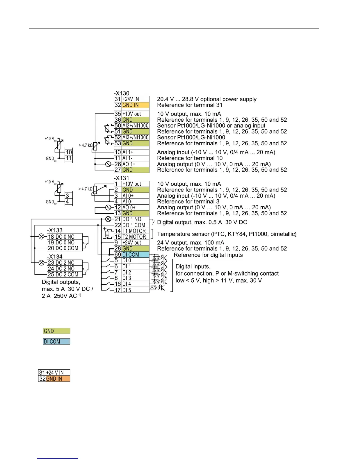
Figure 3-1 Wiring the digital inputs with p-switching contacts and an internal 24 V power supply (terminal 9)
All terminals labelled with reference potential "GND" are connected internally in the inverter.
Reference potential "DI COM" is electrically isolated from "GND". The Control Unit is
delivered with a jumper between terminals 28 and 69.
→ If, as shown above, you wish to use the 24-V supply from terminal 9 as supply for the
digital inputs, then it is mandatory that this jumper is used.
When an optional 24 V power supply is connected at terminals 31, 32, even when the Power
Module is disconnected from the line supply, the Control Unit remains in operation. The
Control Unit thus maintains fieldbus communication, for example.
→ At terminals 31, 32, only connect a power supply that is in accordance with SELV (Safety
Extra Low Voltage) or PELV (Protective Extra Low Voltage).

 Loading...


