Description
3.3 Accessories
Installation and Operating Instructions SINAMICS G180
Operating Instructions, 02/2019, 4BS0751-007
67
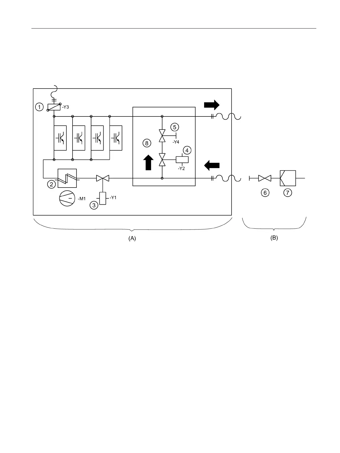
Direct water cooling diagram
Structure
Components in the inverter cabinet
Components provided by the customer
Air / water heat exchanger with fan for interior
Stop valve, regulation of the flow rate
Flow rate regulation valve
Bypass - The version is optional
Figure 3-13 Diagram - Direct water cooling

 Loading...


