Description
3.3 Accessories
Installation and Operating Instructions SINAMICS G180
68 Operating Instructions, 02/2019, 4BS0751-007
Connecting water cooling
Procedure
● Connect the water cooling to the three low-pressure hoses which are installed approx. 2
m above the bottom edge of the cabinet. The hoses are labeled as follows:
– Inlet
– Return flow
– Ventilation
● Install a fine filter with approx. 50 µm mesh size on-site before the inverter.
Venting the water cooling
Procedure
● If counterpressure builds up in the return line, vent the water cooling.
● Also vent the water cooling if it is operated in an enclosed system.
1. Disconnect the inverter before the cooling from the power supply and secure it against
being switched on again.
2. Open the solenoid valve +H1.K2-Y1 to vent the water cooler.
Proceed as follows:
– Open the isolating blade terminals +H1.K1-X5(or X4):12 and …:13.
– At terminals +H1.K1-X5(or X4):11 and …:14 connect an auxiliary power supply
AC 230 V.
– Open the water supply.
– Open the manual valve +H1.K2-Y3 to vent until no more air exits. The valve is located
on the top side at the back on the left.
● Hose bushings and hose clamps are required to establish the connection:
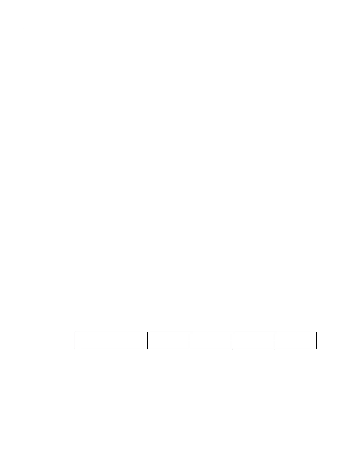
Table 3- 10 Hose sizes
Hose sizes ½ " ¾ " 1 " 1 ½ "

 Loading...


