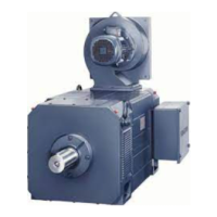
Motor components (options)
5.4 Gearbox
1PH7 induction motors (Machine tools)
Configuration Manual, (APH7W), 04/2009, 6SN1197-0AD72-0BP0
197
5.4.3 Gearbox design
'ULYHKXE
$GDSWHUSODWH
5DGLDOVKDIWVHDOLQJULQJ
+XEEHDULQJ
*HDUER[FDVLQJ
6XQZKHHO
+ROORZZKHHO
+ROORZZKHHOEHDULQJ
%HDULQJKRXVLQJ
2XWSXWEHDULQJ
2XWSXWEHDULQJ
2XWSXWVKDIW
5DGLDOVKDIWVHDOLQJULQJ
3ODQHWDU\ZKHHOFDUULHU
$[LDOEHDULQJZLWKSODWHW\SHVSULQJV
6OLGHFRXSOLQJ
6HOHFWRUIRUN
%UDNHGLVN
6ROHQRLG
6HOHFWRUVKDIW
&RQQHFWLRQSODWH
Figure 5-4 Gearbox design for 1PH7, SH 100 to 160
The following applies to
selector gearboxes:
Switch position I: i1 = 4
Switch position II: i2 = 1
Both gearbox ratios are electrically selected and the setting is monitored using limit switches.
The gearbox output shaft lies coaxially to the motor shaft.
Torsional backlash (measured on gearbox output):
Standard for SH 100-160 30 angular minutes
Standard for SH 180-225 On request
Belt pulley
● The belt pulley should be in the form of a cup wheel.
● The gearbox output shaft has a flange with outer centering and tapped holes to retain the
belt pulley.
● The complete drive should be designed to be as stiff as possible using large belt cross-
sections. This has a positive impact on the smooth running properties of the drive.

 Loading...


