Motor components (options)
5.4 Gearbox
1PH7 induction motors (Machine tools)
204 Configuration Manual, (APH7W), 04/2009, 6SN1197-0AD72-0BP0
Table 5- 9 Flange dimensions for motors
Standard motor companion dimensions Two-stage
Selector gearbox
Size
h d l b e
2
a
1
s
2
2K120 101, 103, 105, 107 100
–0.5
38 k
6
80 180 j
6
215
±0.5
– 14
±0.2
2K250 131, 132, 133, 135, 137 132
–0.5
42 k
6
110 250 h
6
300
±0.5
– 18
±0.2
2K300 163, 167 160
–0.5
55 k
6
110 300 h
6
350
±0.5
– 18
±0.2
2K800 184 On request
2K801 186 On request
2K802 224 On request
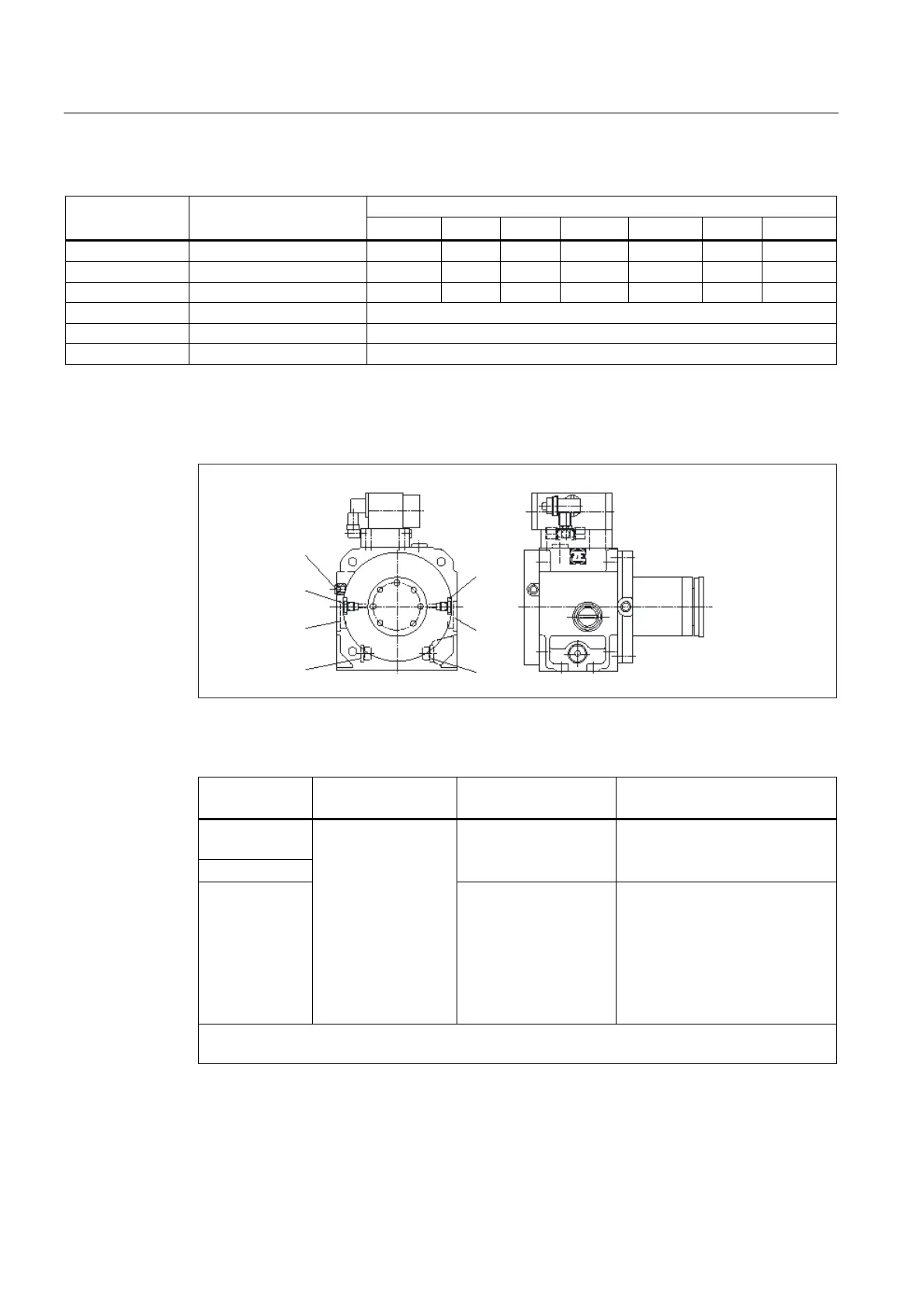
5.4.9 Connections, circulating oil lubrication, frame size 100
M
K
E
G
L
D
F
Figure 5-9 Selector gearbox with selector unit for frame size 100
Table 5- 10 Connections for circulating oil lubrication
Max. pressure Connection
Oil return
Connection
Oil inlet
Mounting position
0.2 bar
1.5 bar
1.5 bar
M (0.5 dm
3
/min)
K/L (1.0 dm
3
/min)
V1
(closed version)
1.5 bar
D
Main direction of
rotation
Clockwise
1)
E
Main direction of
rotation
Counter-clockwise
1)
G (1.5 dm
3
/min)
Main direction of
rotation
clockwise
F (1.5 dm
3
/min)
Main direction of
rotation
counter-clockwise
B5
V1
Note: Circulating oil lubrication is required for certain gearboxes and V1 or V3 vertical mounting
positions (refer to Chapter "Lubrication")
1)
When viewing the gearbox drive from the motor

 Loading...


