Connection system
6.5 Supply data for separately-driven fans
1PH7 induction motors (Machine tools)
218 Configuration Manual, (APH7W), 04/2009, 6SN1197-0AD72-0BP0
6.5 6.5 Supply data for separately-driven fans
Table 6- 5 Supply data for separately-driven fans
Shaft
height
Air flow direction Max. current drain at
400 V/50 Hz
(±10%)
400 V/60 Hz
(±10%)
480 V/60 Hz
(±5%, -10%)
DE --> NDE 0.20 0.13 0.20 100
NDE --> DE 0.19 0.13 0.18
DE --> NDE 0.37 0.24 0.33 132
NDE --> DE 0.35 0.24 0.32
DE --> NDE 0.30 0.33 0.34 160
NDE --> DE 0.29 0.31 0.33
DE --> NDE 0.8 1.1 1.1 180
NDE --> DE 0.8 1.1 1.1
DE --> NDE 2.8 2.8 2.8 225
NDE --> DE 1.9 2.2 2.2
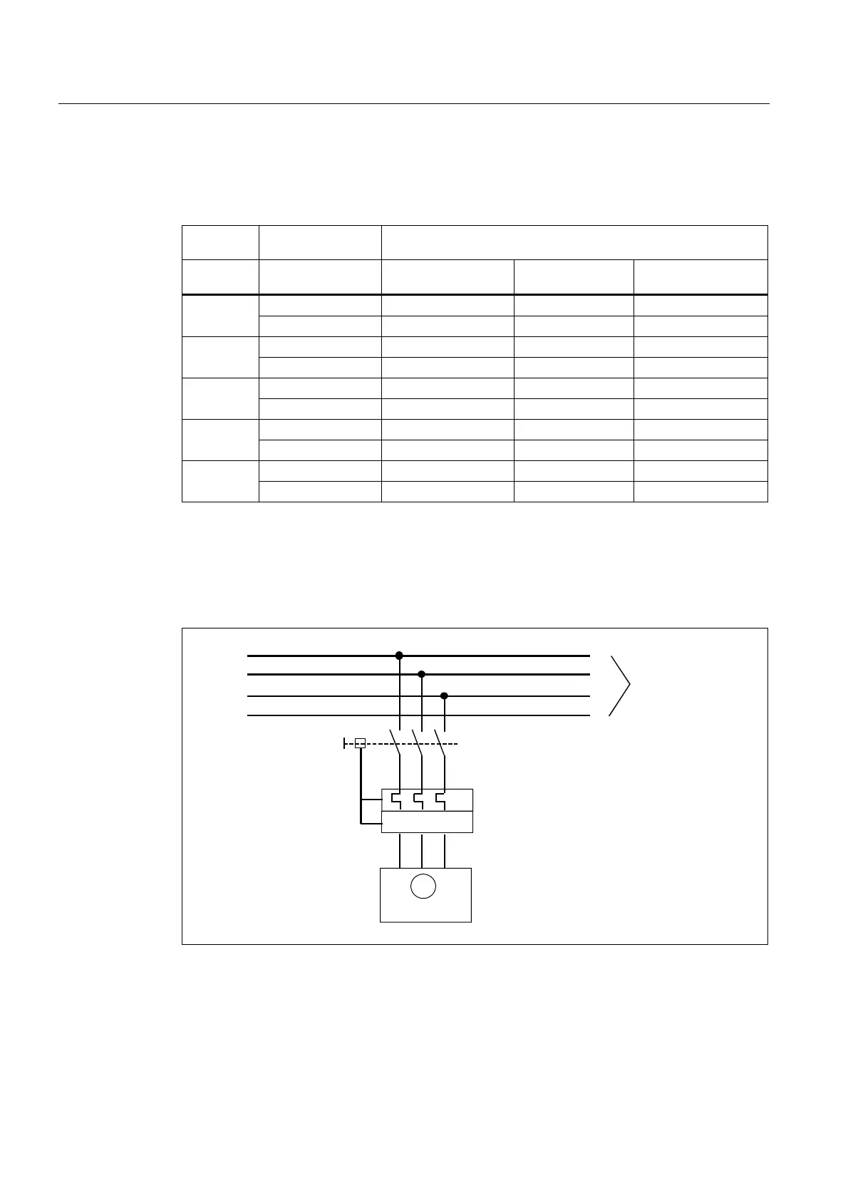
Recommended connection
The connection is realized through the terminal box or through the terminal box of the
separately-driven fan. The fan should be operated through motor protection circuit-breakers.
The tripping current must be set to the I
max
value of the fan.
8 9 :
3(
/
/
/
0
!,
$GGLWLRQDOIDQV
7KHPRWRUSURWHFWLRQFLUFXLWEUHDNHULV
QRWLQFOXGHGZLWKWKHPRWRU
)DQV
Figure 6-5 Recommended connection

 Loading...


