Mechanical properties of the motors
3.1 Cooling
1PH7 induction motors (Machine tools)
50 Configuration Manual, (APH7W), 04/2009, 6SN1197-0AD72-0BP0
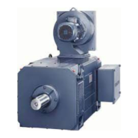
Mounting a fan and minimum clearance to the customers mounted parts and components
Table 3- 2 Fan mounting
Shaft height [mm] Fan mounting
100 to 225 NDE axial, can be rotated through 4 x 90°
The minimum clearance to the customer's mounted parts and components and the air
discharge opening as well as the minimum clearance S between the air intake and air
discharge openings and adjacent components must be maintained.
Table 3- 3 Minimum clearances
Shaft height
[mm]
Minimum clearance to the
customer's mounted parts and
components [mm]
Minimum clearance S
[mm]
100 30 30
132 60 60
160 80 80
180 100 80
225 100 80
6
Air flow rate, air flow direction and air discharge
Table 3- 4 Air flow rate, air flow direction and air discharge
Shaft height
[mm]
Air flow
direction
Required air flow rate [m
3
/s] Air
discharge
Pressure drop
(Δp) [Pa]
NDE → DE 0.04 Axial 100
DE → NDE 0.04 Axial
on request
NDE → DE 0.1 Axial 132
DE → NDE 0.1 Axial
on request
NDE → DE 0.15 Axial 160
DE → NDE 0.15 Axial
on request
NDE → DE 0.19 Axial 650 180
DE → NDE 0.19 Radial 650
NDE → DE 0.36 Axial 225
DE → NDE 0.36 Radial
900
Note
If the ambient air is polluted by particles of dust or similar substances, then the preferable air
flow direction is NDE → DE.

 Loading...


