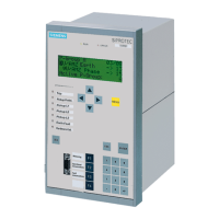
7SJ61...7SJ63, 7SJ65, 6MD63 PROFIBUS-DP – Bus mapping
C53000-L1840-B006-02
7-1
7 Index
Index
Numerics
27..............................................................2-8
37-1 Undercurrent alarm....................3-8, 4-6
46.......................................................2-7, 3-7
49............................................. 2-9, 3-7, 5-14
50/51........................................ 2-6, 3-6, 5-13
50BF ..................................................2-8, 3-7
50Ns......................................... 2-8, 3-7, 5-14
51Ns...................................................2-8, 3-7
55 Power factor alarm........................3-8, 4-6
59..............................................................2-8
64..............................................................2-8
66.......................................................2-9, 3-7
67.....................................................2-7, 5-14
74TC ..................................................2-9, 3-8
79.......................................................2-6, 3-6
81..............................................................2-7
A
additional manuals........................................ i
Alarm summary event.............................1-13
Automatic recloser status ..................2-6, 3-6
B
binary inputs..............................................1-3
C
CFC-Incoming annunciation ...... 2-2, 3-2, 4-2
CFC-Output indication ............... 2-5, 3-5, 4-5
Circuit breaker failure protection........2-8, 3-7
Cold-load-pickup................................2-9, 3-8
command outputs1-3
configuration data .....................................1-7
control authority .............................1-11, 2-10
Control mode .........................................2-10
Control mode REMOTE..........................1-11
D
definitions of data types ............................1-2
Double commands....................................3-1
Directional time overcurrent protection.....2-7
Double-point indication .............. 2-4, 3-4, 4-4
E
Error with a summary alarm....................1-12
F
Fault locator............................................2-12
Frequency protection................................2-7
M
Measured values ...1-4, 2-11, 3-10, 4-8, 5-15
Measurement supervision ......................2-10
Metered measurands...... 1-5, 2-12, 3-10, 4-9
Motor start protection.........................2-9, 3-7
O
operating hours meter ..............................1-5
output relays .............................................1-3
Overvoltage protection..............................2-8
S
Sensitive ground fault protection .......2-8, 3-7
Set point..................................................2-10
setting group...........................................1-11
Single commands............................1-10, 3-1
Single-point indication................ 2-4, 3-4, 4-4
standard mapping..............................1-6, 1-9
Startup supervision............................2-9, 3-7
Stop data transmission...........................1-13
switching devices‘ status ..........................1-3
T
Thermal overload protection.... 2-9, 3-7, 5-14
Time overcurrent protection..... 2-6, 3-6, 5-13
Trip coil monitor ........................................2-9
U
Unbalanced load protection...............2-7, 3-7
Undervoltage protection............................2-8
V
Validity ..........................................................ii

 Loading...


