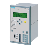
7SJ61...7SJ63, 7SJ65, 6MD63 PROFIBUS-DP – Bus mapping
C53000-L1840-B006-02
vii
3.2.1.15 Cold load pickup .........................................................................................................3-8
3.2.1.16 Measurement supervision...........................................................................................3-8
3.2.1.17 Set point alarms..........................................................................................................3-8
3.2.1.18 Status annunciations ..................................................................................................3-9
3.2.2 Measured values.......................................................................................... 3-10
3.2.2.1 Recorded measured values ......................................................................................3-10
3.2.2.2 Measured values – mean values...............................................................................3-10
3.2.3 Metered measurands ................................................................................... 3-10
4 Standard mapping 2-3 ................................................................................................... 4-1
4.1 Message in output direction ........................................................................... 4-1
4.1.1 Double commands (with checkback indication)............................................. 4-1
4.1.2 Single commands (without checkback indication) ......................................... 4-1
4.1.3 Internal commands ........................................................................................ 4-2
4.1.4 Application logic CFC..................................................................................... 4-2
4.2 Message in input direction ............................................................................. 4-4
4.2.1 Annunciations................................................................................................. 4-4
4.2.1.1 Double commands – checkback signals.....................................................................4-4
4.2.1.2 Single commands – status..........................................................................................4-4
4.2.1.3 Input channels with allocation to the binary inputs and tagging..................................4-5
4.2.1.4 Application logic CFC..................................................................................................4-5
4.2.1.5 Diagnosis ....................................................................................................................4-6
4.2.1.6 Measurement supervision ...........................................................................................4-6
4.2.1.7 Set point alarms ..........................................................................................................4-6
4.2.1.8 Status annunciations...................................................................................................4-7
4.2.2 Measured values............................................................................................ 4-8
4.2.2.1 Recorded measured values ........................................................................................4-8
4.2.2.2 Measured values – mean values.................................................................................4-8
4.2.3 Metered measurands ..................................................................................... 4-9
5 Standard mapping 2-4 ................................................................................................. 5-11
5.1 Message in output direction ......................................................................... 5-11
5.1.1 Double commands (with checkback indication)........................................... 5-11
5.1.2 Single commands (without checkback indication) ....................................... 5-11
5.1.3 Internal commands ...................................................................................... 5-11
5.1.4 Application logic CFC................................................................................... 5-12
5.2 Message in input direction ........................................................................... 5-13
5.2.1 Annunciations............................................................................................... 5-13
5.2.1.1 Double commands – checkback signals...................................................................5-13
5.2.1.2 Single commands – status........................................................................................5-13
5.2.1.3 Application logic CFC................................................................................................5-13
5.2.1.4 Time overcurrent protection ......................................................................................5-13

 Loading...


