• 2 properly executed drill holes with thread or plugs on the level surface. Refer to the drilling
pattern (Page 287).
• 2 head screws M4 x 12 DIN ISO 7045 to t the drill-holes
• Screwdriver (depending on the drive of the screws)
• 2 push-in lugs (accessories) for wall mounting
• HMI connecting cable (accessory) of suitable length connected to the 3RW55 or 3RW55
Failsafe soft starter
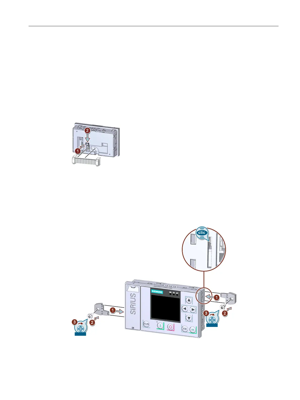
Procedure
• Observe the coding of the plug and socket ①.
• Lock the connector in the socket ②.
• The HMI connecting cable in the cable duct of the 3RW5 HMI High Feature may only be routed
downward.
Make sure that you install the cable in accordance with EMC requirements. For example,
install data cables separately from the motor cable. Connect both sides of shielded cables
over a large surface area.
• Insert the push-in lugs into each side of the enclosure until you hear them engage ① and x
the 3RW5 HMI High Feature on the wall ② / ③.
Mounting and dismantling
4.4 Installing, mounting and removing the 3RW5 HMI High Feature
SIRIUS 3RW55 and 3RW55 Failsafe Soft Starters
Equipment Manual, 02/2022, A5E35630887002A/RS-AF/006 63

 Loading...


