Basic information about the drive system
13.12 System rules, sampling times and DRIVE-CLiQ wiring
Drive functions
1012 Function Manual, 11/2017, 6SL3097-4AB00-0BP5
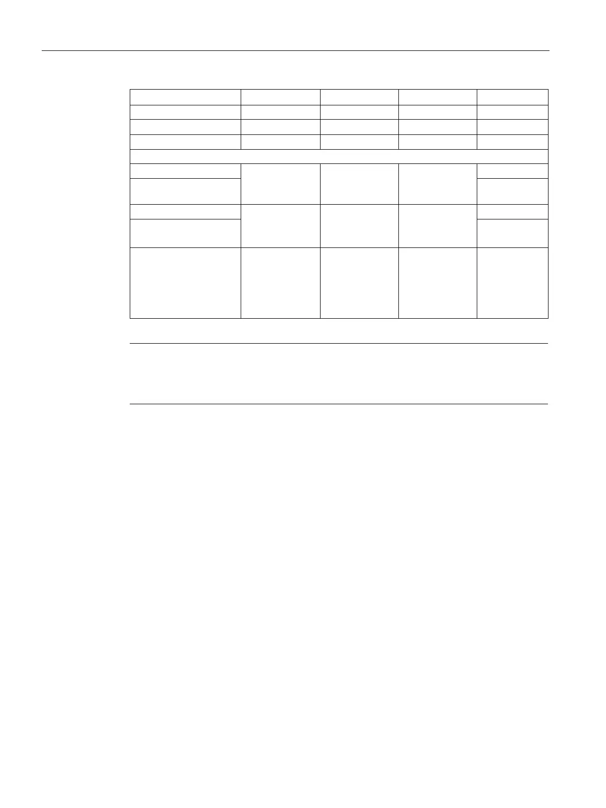
Chassis 1 ... 6 1 (xLow) 250 µs 2 kHz
1 ... 3 only n_ctrl
1 ... 6 only V/f
3 (Standard) 250 µs
Chassis
2 kHz
4 ... 6 only n_ctrl
0 (Expert) 500 µs
Chassis
400 V / ≤ 250 kW
2 kHz
Chassis
400 V / > 250 kW
690 V
1 ... 4 only n_ctrl
1 ... 5 only V/f
5 ... 6 only n_ctrl
0 (Expert)
1 (xLow)
0 (Expert)
375 µs (p0092 =
1)
400 µs (p0092 =
0)
500 µs (p0092 =
1.333 kHz
1.25 kHz
1.0 kHz
Note
If a Power Module Blocksize is connected to a Control Unit, the sampling times of all vector
drives are set according to the rules for Power Modules Blo
cksize (only 250 µs or 500 µs
Setting the pulse frequency
The sampling times for the following functions are set by selecting the appropriate values in
p0112 for the closed-loop control configuration in µs and are copied to p0115[0...6]
depending on the performance levels required:
● Current controller (p0115[0])
● Speed controller (p0115[1])
● Flux controller (p0115[2])
● Setpoint channel (p0115[3])
● Position controller (p0115[4])
● Positioner (p0115[5])
● Technology controller (p0115[6])
The performance levels range from xLow to xHigh. Details of how to set the sampling times
are given in the SINAMICS S120/S150 List Manual.
 Loading...


