Safety Integrated Basic Functions
10.9 Control via TM54F
Drive functions
Function Manual, 11/2017, 6SL3097-4AB00-0BP5
703
You have the following options of acknowledging TM54F faults after troubleshooting:
● POWER ON
● Falling edge of the signal "Internal Event ACK" with subsequent acknowledgment on the
Control Unit ("fail-safe acknowledgment").
F-DI function
Description
Fail-safe digital inputs (F-DI) consist of 2 digital inputs. At the 2nd digital input, the cathode
(M) of the optocoupler is additionally brought out to enable connection of an output of a fail-
safe control grounded through a switch. (The anode must be connected to 24 V DC).
Parameter p10040 is used to determine whether an F-DI is operated as NC/NC or NC/NO
contact. The status of each DI can be read at parameter r10051. The bits of both drive
objects are logically AND'ed and return the status of the relevant F-DI.
Test signals from F-DOs and interference pulses can be filtered out using the input filter
(p10017), so that they do not cause any faults.
to select the safety function, a "zero level" must be present at both
inputs.
to select the safety function, a "zero level" must be present at input
1 and a "1 level" at input 2.
The signal states at the two associated digital inputs (F-DI) must assume the same status
configured in p10040 within the monitoring time set in p10002.
In order to enable forced checking procedure (test stop), connect the digital inputs of F-DI 0
... 4 of the TM54F with the dynamic voltage supply L1+ and the digital inputs with F-DI 5 ... 9
to L2+ (for additional information on forced checking procedure (test stop), see the
corresponding function description in Section "Forced checking procedure (test stop)
(Page 677)").
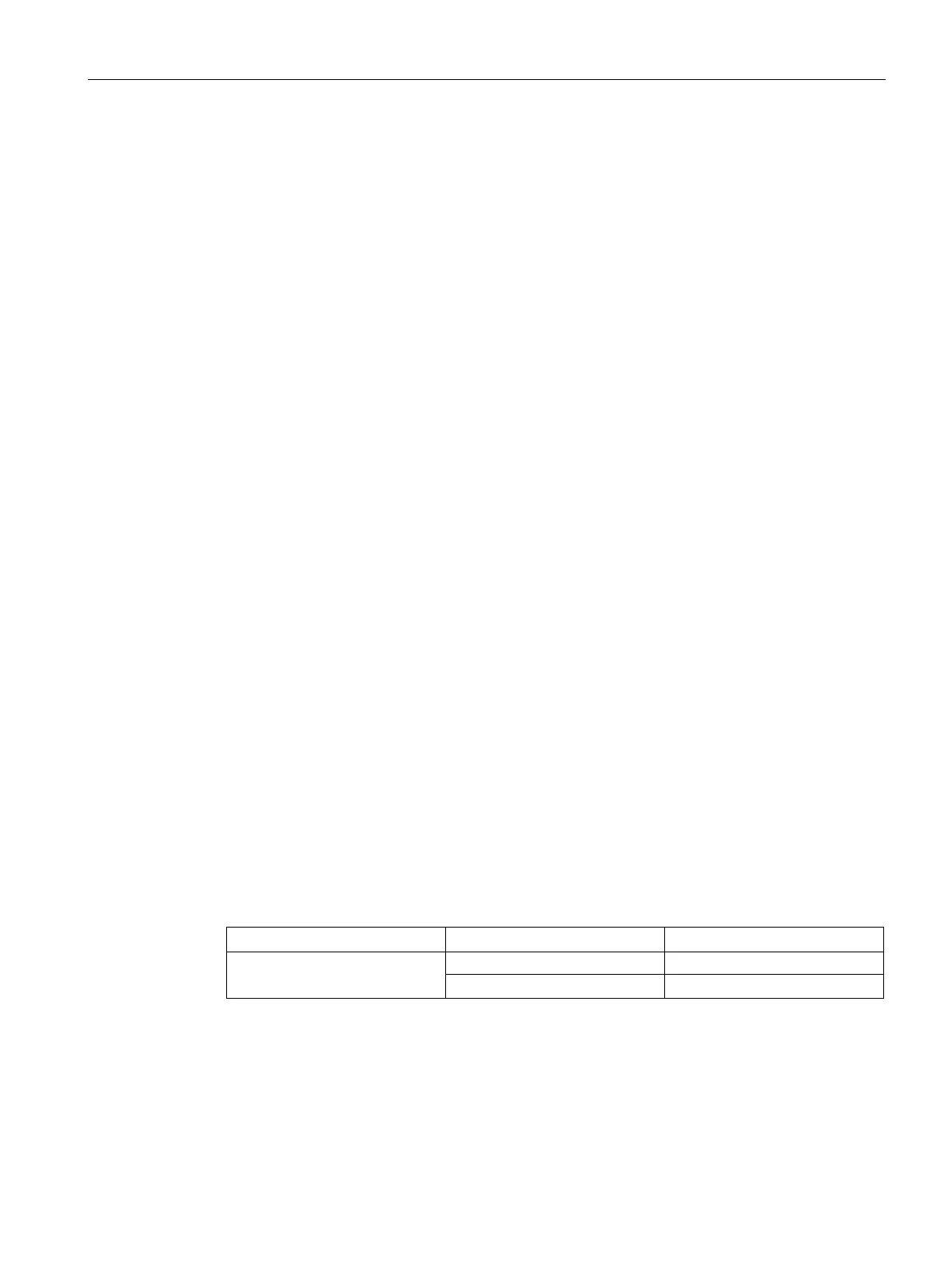
Table 10- 7 Overview of the fail-safe inputs in the SINAMICS S120/S150 List Manual:
TM54F
2894 F-DI 5 ... 9
 Loading...


