Electrical installation
4.5 Connections
Cabinet Modules NEMA
80 Manual, 04/2014, A5E03586450A
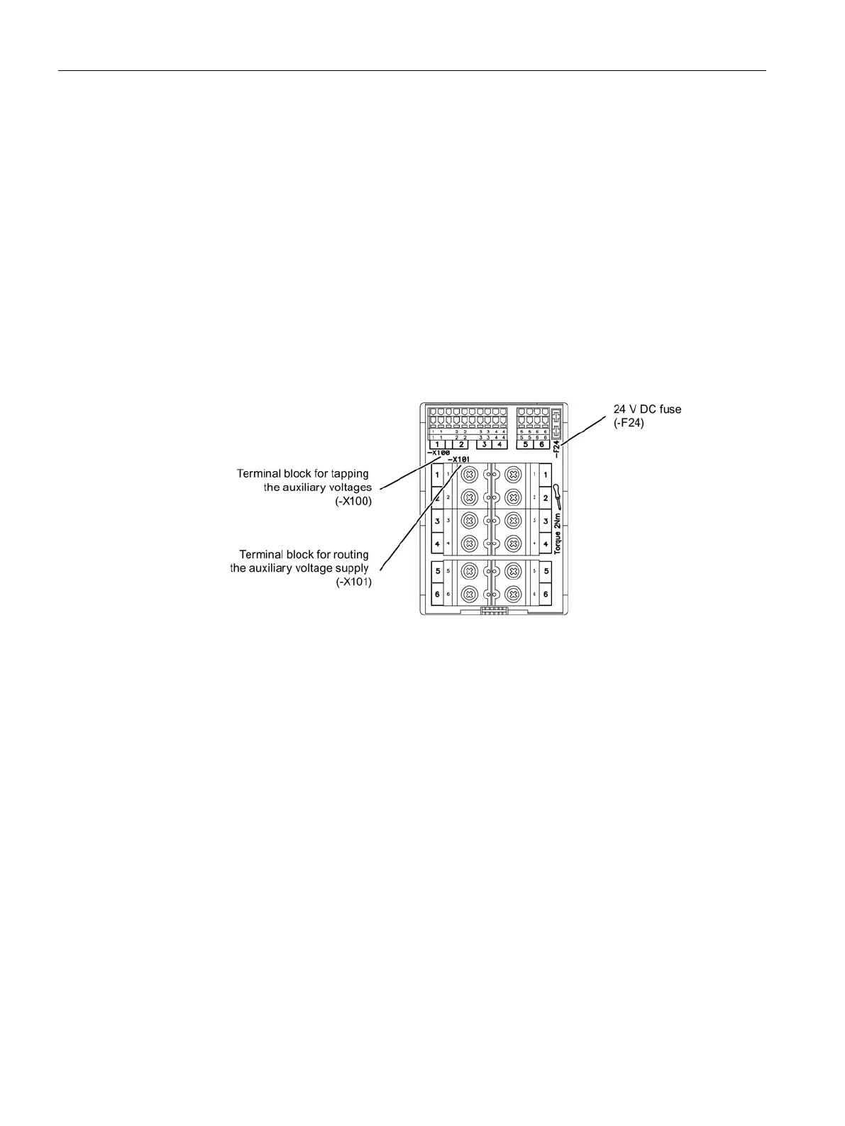
The auxiliary power module comprises two terminal blocks (-X100, -X101) and one fuse (-
F24) for the 24 V DC supply. The auxiliary power module is used to tap the necessary
auxiliary voltages at terminal block -X100 and to forward auxiliary voltages to terminal block
-X101 in the adjacent cabinet unit.
The connections are made using two special cables. One 4-phase cable for the line voltage
(1, 2) and for 230 V AC (3, 4), and an additional screened 2-phase cable for 24 V DC (1, 2).
The auxiliary power supply system is ready-to-operate as supplied. The cabling required
from the terminal block into the relevant Cabinet Module are factory-installed. Only the
connection to the adjacent Cabinet Module must be established on site by fastening the
cables to the next terminal block. These connections are already established within transport
units. Only the transport units need to be interconnected.
Figure 4-7 Auxiliary power module with terminal blocks -X100, -X101 and 24 V DC fuse
At least two terminals are always available to the customer at terminal block -X100 for
tapping the auxiliary voltages.
 Loading...


