Description, device design, dimension drawing
2.7 Operator controls
Power supply system SITOP PSU8600
Manual, 09.2018, A5E36758446-5-76
43
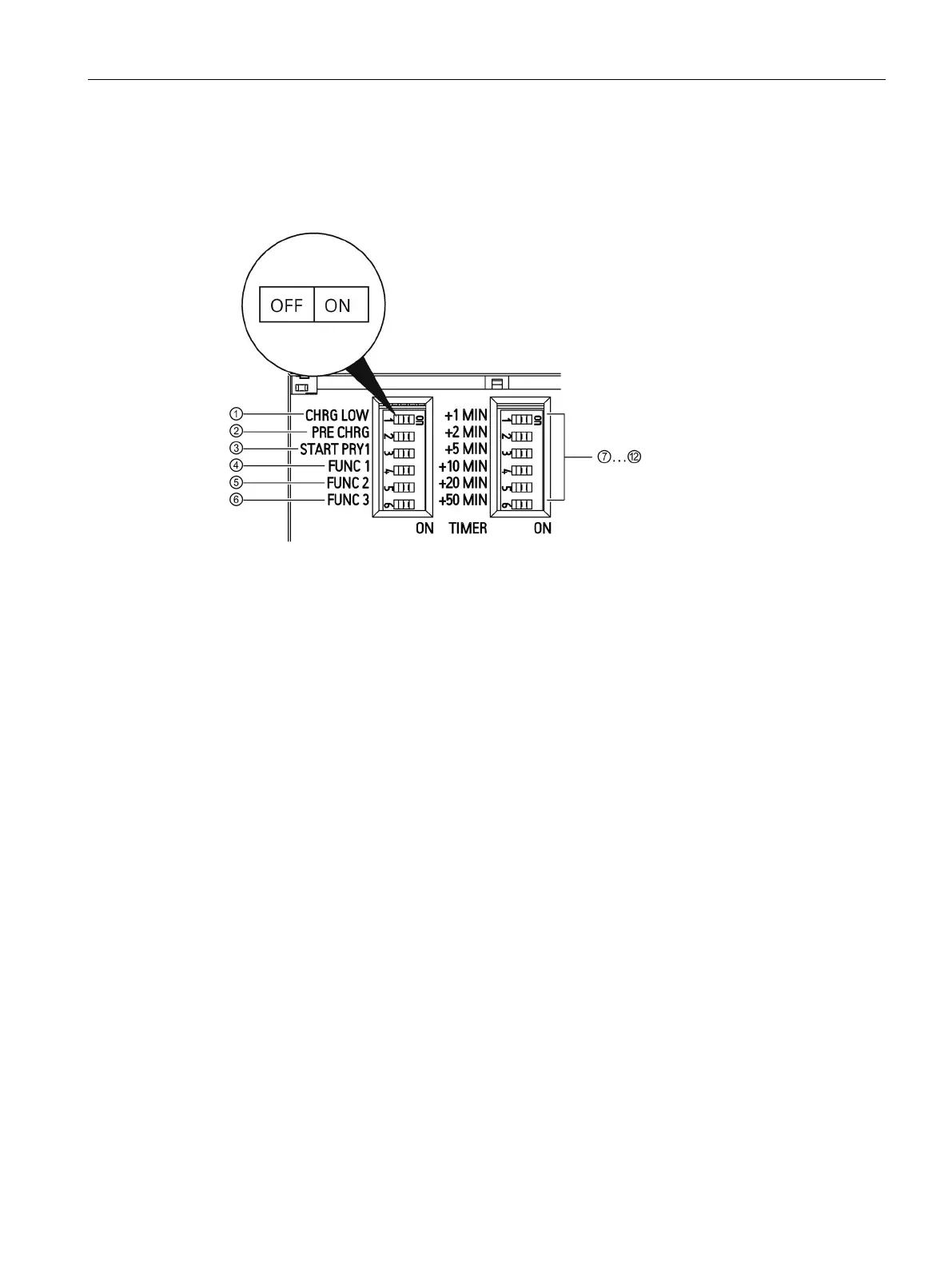
DIP switches ① to ⑥, used to activate the special functions, and DIP switches ⑦ to ⑫,
used to enter the buffer time limiting, are provided on the front side of the UPS module.
DIP switch
Sets the charging power; see Chapter "Setting the charging power of the
DIP switch
PRE CHRG
Sets the precharge function. Selects whether the batteries are first
charged to a specified value before the system outputs are activated;
see Chapter "Selecting the preferred charging mode for a system start
DIP switch
START PRY1
Only output 1 is activated when starting from the battery modules; see
Chapter "When starting from the battery, only output 1 is activated
DIP switch
No function
DIP switch
No function
DIP switch
No function
…
DIP switch
DIP switch to set the time, which when it expires, buffer mode is exited;
see Chapter "Specifying the buffer time limiting (Page 107)".
A transparent plastic cover protects the DIP switches from inadvertent actuation. When
required, this plastic cover can be sealed to prevent the DIP switches being actuated by
unauthorized personnel. To seal, the sealing wire is routed through an opening in the plastic
cover and housing.

 Loading...


