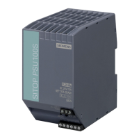
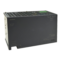
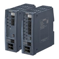
SITOP SEL1200-1400
Equipment Manual, 06.2020, A5E46496083-2-76
7
Overview................................................................................................................................................. 3
1 Safety instructions ................................................................................................................................... 9
1.1 General safety instructions ....................................................................................................... 9
1.2 Safety instructions for hazardous zones ................................................................................. 10
2 Description, device design, dimension drawing...................................................................................... 11
2.1 Device description ................................................................................................................... 11
2.2 Connections and terminal designation.................................................................................... 13
2.3 Potentiometer .......................................................................................................................... 15
2.4 Status displays and signaling ................................................................................................. 16
2.5 Buttons and selector switches ................................................................................................ 19
2.6 Electronic overload shutdown and reset ................................................................................. 21
2.7 Setting the switch-on delay time ............................................................................................. 24
2.8 Block diagram ......................................................................................................................... 25
2.9 Dimensions and weight ........................................................................................................... 26
3 Mounting/removal ................................................................................................................................. 29
4 Mounting position, mounting clearances ................................................................................................ 31
4.1 Standard mounting position .................................................................................................... 31
4.2 Other mounting positions ........................................................................................................ 34
4.2.1 SEL1200 8 x 5 A 6EP4437-7FB00-3DX0 ............................................................................... 34
4.2.2 SEL1200 4 x 10 A 6EP4437-7FB00-3CX0 ............................................................................. 36
4.2.3 SEL1200 8 x 10 A 6EP4438-7FB00-3DX0 ............................................................................. 38
4.2.4 SEL1400 8 x 5 A 6EP4437-7EB00-3DX0 ............................................................................... 40
4.2.5 SEL1400 4 x 10 A 6EP4437-7EB00-3CX0 ............................................................................. 42
4.2.6 SEL1400 8 x 10 A 6EP4438-7EB00-3DX0 ............................................................................. 44
5 Installation ............................................................................................................................................ 47
5.1 Connection at the input ........................................................................................................... 47
5.2 Connection at the output ......................................................................................................... 49
6 Technical data ...................................................................................................................................... 51
6.1 Input ........................................................................................................................................ 51
6.2 Output ..................................................................................................................................... 52
6.3 Efficiency ................................................................................................................................. 54
6.4 Protection and monitoring ....................................................................................................... 54
6.5 MTBF ...................................................................................................................................... 54
 Loading...
