SIMATIC STEP 7 function blocks
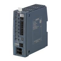
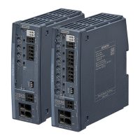
5.10 FB SITOP_PSU8600_MainUnitSingle
SITOP PSU8600 Firmware V1.4: Faceplates and Communication Blocks V2.4 for SIMATIC STEP 7 V14 SP1, V15 and V15.1 (TIA)
50 Function Manual, 11.2018, A5E37763954-09-76
Bool On the rising edge (0 > 1), data at the
inputs of the block is written to the PSU.
HW_IO Start address of the entire main module.
(Reference, system tag: PSU_1 refers to
the assigned PROFINET device name of
memory_address
HW_IO Address of main module IO data sub-
module.
(Reference, system tag: <PSU Device
Name>~PSU8600_IO_Data_submodule.
For example:
PSU_1~PSU8600_IO_Data_submodule)
UDT for device input parameters.
Structure of UDT_General_PSUSingle_IN data type
Channel_1
Byte During a network failure, output 1 of the main module can
be supplied with priority.
Byte Switch-on behavior
0 = no switch-on delay
1 = switch-on delay 25 ms
2 = switch-on delay 100 ms
3 = load-optimized switch-on delay
4 = variable switch-on delay
Byte Pre-alarming threshold (0 to 100 %) for alarming.
Byte Outputs are switched off due to overload and are switched
on again when they are ready for it.
0 = normal state (no actions taken)
1 = switched on again.
The value must be reset to 0 after switching on.
Characteristic
Byte Soft Output Characteristics (False = 0, True = Any non
SystemOv-
erloadAlarmThreshold
UInt System overload alarm threshold time (0 to 60000 ms)
MainPowerOuta-
geThreshold
UInt Main power outage alarm threshold time (0 to 1000 ms)
 Loading...
